Tampa Water Department Development Manual
E_1.2_TWD Development Manual_20210209
AUTHOR: Brian Pickard

DATE: 2/9/2021
COLLABORATORS: Seung Park, Chad Bailey, Rory Jones, Juan Alvira, Charles Gallo
APPROVER
PRINTED NAME: Charles J. Weber
TITLE: Director
APPROVER
EFFECTIVE

SIGNATURE: _________________________
DATE: ____________________
NEXT REVIEW DATE: 2/9/2026
1.0 Department Procedures
- Department Procedures .................................................................................................................. 9
- Generalized Customer-Initiated Project Workflow .................................................................... 10
- Water Service Application Requirements.................................................................................. 17
- When a Utility Service Application is Required...................................................................... 17
- Utility Service Application Submittal Guidelines .................................................................... 18
- Portable Hydrant Meter Application Submittal Guidelines..................................................... 21
- Utility Service Application Review.......................................................................................... 21
- Water Service Commitment Generation and Issuance ......................................................... 22
- City vs Developer-Installed Projects.............................................................................. 22
- Siting.............................................................................................................................. 22
- Special Areas .......................................................................................................... 22
- Sizing ............................................................................................................................. 22
- Fees............................................................................................................................... 23
- Application and Review Fees .................................................................................. 23
- Connection Fees ..................................................................................................... 23
- Service Installation Fees ......................................................................................... 23
- Abandoned Service Renewals ................................................................................ 23
- Deposits................................................................................................................... 25
- Meter Drop-In Fees ................................................................................................. 25
- Large Meter Furnishing Fees .................................................................................. 25
- City Installation Cost Estimates............................................................................... 25
- Aid In Construction Fees ......................................................................................... 26
- Capacity Fees.......................................................................................................... 30
- Permit Fees ............................................................................................................. 30
- Inspection Fees ....................................................................................................... 30
- Fire Readiness to Serve Fees................................................................................. 31
- Temporary / Construction Service Fees.................................................................. 31
- Meter Relocation Fees ............................................................................................ 31
- Connection Fee Financing............................................................................................. 31
- Accepted Payment Forms and Payment Locations ...................................................... 31
- NSF / Insufficient Funds Situations ............................................................................... 32
- Refunds ......................................................................................................................... 32
- Utility Service Authorization Forms................................................................................ 32
- City-Installed Target Time Frames ................................................................................ 33
- Cross Connection Control ............................................................................................. 33
- 1.2.6 Design .................................................................................................................................... 34
- 1.2.7 Third Party Permitting ............................................................................................................ 35
- 1.2.7.1 City-Installed .................................................................................................................. 35
- 1.2.7.2 Developer-Installed........................................................................................................ 35
- 1.2.8 Construction ........................................................................................................................... 36
- 1.2.8.1 Material Submittals and Pre-Construction Meeting ....................................................... 36
- 1.2.8.2 Hydrostatic and Bacteriological Tests ........................................................................... 37
- 1.2.8.3 Clearance Application.................................................................................................... 37
- 1.2.9 Developer Agreements .......................................................................................................... 37
- 1.2.10 Project Closeout..................................................................................................................... 38
- 1.2.10.1 Record Drawings ........................................................................................................... 38
- 1.2.10.2 Closeout Checklist ......................................................................................................... 39
- 1.3 Plat and / or Master Planned Developments............................................................................. 39
- 1.3.1 Preliminary Plat Requirements .............................................................................................. 40
- 1.3.2 Final Plat Requirements......................................................................................................... 40
- 1.3.3 Community Master Plan Requirements ................................................................................. 40
- 1.3.3.1 Components .................................................................................................................. 40
- 1.3.3.2 Phasing.......................................................................................................................... 41
- 1.3.3.3 Hydraulic Modeling ........................................................................................................ 41
- 1.4 Right-of-Way Vacates, Right-of-Way Encroachments, and Easement Releases..................... 41
- 1.5 Demolition Permits .................................................................................................................... 42
- 1.6 Rezoning.................................................................................................................................... 42
- 1.7 Comprehensive Plan Amendments ........................................................................................... 42
- 1.8 Food Truck Approvals ............................................................................................................... 42
- 1.9 Requesting As-Builts ................................................................................................................. 42
- 1.10 Requesting Fire Hydrant Flow Tests ......................................................................................... 42
- 1.11 Building Permit Holds ................................................................................................................ 42
- 1.12 Easement Acquisition ................................................................................................................ 43
- 2.0 Material, Workmanship, and Other Specifications ........................................................................ 44
- 2.1 Drafting ...................................................................................................................................... 44
- 2.1.1 General .................................................................................................................................. 44
- 2.1.1.1 Drawing Size.................................................................................................................. 44
- 2.1.1.2 Drawing Scales.............................................................................................................. 44
- 2.1.1.3 Plan and Profile Views................................................................................................... 44
- 2.1.1.4 Survey and State Plane Requirements ......................................................................... 45
- 2.1.1 General .................................................................................................................................. 44
- 2.1 Drafting ...................................................................................................................................... 44
- 2.1.1.5 Construction Drawing Checklist..................................................................................... 45
- 2.1.1.5.1 Pipeline.................................................................................................................... 45
- 2.1.1.5.2 General Requirements ............................................................................................ 46
- 2.1.1.5.3 Valves, Fittings, Taps .............................................................................................. 46
- 2.1.1.5.4 Hydrants and Meter Services .................................................................................. 47
- 2.2 Design Standards ...................................................................................................................... 47
- 2.2.1 General .................................................................................................................................. 47
- 2.2.2 Pipe ........................................................................................................................................ 47
- 2.2.2.1 Sizing Assumptions ....................................................................................................... 47
- 2.2.2.2 Sizing Criteria ................................................................................................................ 48
- 2.2.2.3 Water Quality ................................................................................................................. 49
- 2.2.2.4 Clearances and Separations ......................................................................................... 50
- 2.2.2.5 Conflict Manholes .......................................................................................................... 51
- 2.2.2.6 Property Frontage Requirements for Water Main Extensions....................................... 52
- 2.2.2.6.1 New Buildings.......................................................................................................... 52
- 2.2.2.6.2 Existing Buildings .................................................................................................... 52
- 2.2.3 Valves .................................................................................................................................... 52
- 2.2.3.1 Air Release Valves ........................................................................................................ 52
- 2.2.3.2 Blow-Off Valve Assemblies ........................................................................................... 52
- 2.2.4 Fire Hydrants ......................................................................................................................... 53
- 2.2.4.1 Fire Protection ............................................................................................................... 53
- 2.2.4.2 Water Quality ................................................................................................................. 53
- 2.2.5 Service Connections .............................................................................................................. 53
- 2.2.5.1 When and How Many Are Permissible.......................................................................... 53
- 2.2.5.2 Consecutive Water Supplies ......................................................................................... 54
- 2.2.5.3 Sizing ............................................................................................................................. 54
- 2.2.5.3.1 Meters and Service Lines ........................................................................................ 54
- 2.2.5.3.2 Fire Lines ................................................................................................................. 59
- 2.2.5.3.3 Equivalent Meter Sizes for Combined Domestic/Fire Services............................... 60
- 2.2.5.4 Site and Siting Requirements ........................................................................................ 60
- 2.2.6 Construction Standards ......................................................................................................... 62
- 2.2.6.1 Contractor Requirements .............................................................................................. 62
- 2.2.6.2 Site Preparation ............................................................................................................. 63
- 2.2.6.3 Dewatering..................................................................................................................... 64
- 2.2.6.4 Maintaining Service and Shutdowns ............................................................................. 64
- 2.2.6.5 Trenching, Backfilling and Compacting ......................................................................... 64
- 2.2.6.5.1 Impervious (Paved) Surface Areas ......................................................................... 65
- 2.2.6.5.2 Pervious (Non-Paved) Surface Areas ..................................................................... 66
- 2.2.6.6 Pipeline Installation........................................................................................................ 66
- 2.2.6.6.1 General .................................................................................................................... 66
- 2.2.6.6.2 Underground Pipelines ............................................................................................ 66
- 2.2.6.6.3 Above Ground and Exposed Piping ........................................................................ 70
- 2.2.6.7 Casing Installation ......................................................................................................... 70
- 2.2.6.8 Fittings ........................................................................................................................... 71
- 2.2.6.8.1 Anchorage of Tees, Bends and Plugs..................................................................... 72
- 2.2.6.9 Valves ............................................................................................................................ 72
- 2.2.6.10 Taps............................................................................................................................... 73
- 2.2.6.11 Hydrants ........................................................................................................................ 74
- 2.2.6.11.1 Installation ............................................................................................................... 74
- 2.2.6.11.2 Protection Posts ...................................................................................................... 74
- 2.2.6.12 Backflow Preventers ...................................................................................................... 74
- 2.2.7 Requirements for Acceptance ............................................................................................... 75
- 2.2.7.1 General .......................................................................................................................... 75
- 2.2.7.2 Testing ........................................................................................................................... 75
- 2.2.7.2.1 Hydrostatic Testing.................................................................................................. 75
- 2.2.7.2.2 Disinfection .............................................................................................................. 77
- 2.2.7.2.3 Sampling.................................................................................................................. 78
- 2.2.7.3 Restoration .................................................................................................................... 78
- 2.2.7.3.1 Waste Material Disposal.......................................................................................... 78
- 2.2.7.3.2 Repair and Resurfacing........................................................................................... 79
- 2.2.7.3.2.1 City of Tampa Owned Right-of-Way Requirements ....................................... 79
- 2.2.7.3.2.2 Non-City of Tampa Owned Right-of-Way Requirements ............................... 84
- 2.2.7.3.3 Pavement and Marking ........................................................................................... 84
- 2.2.7.3.4 Street and Traffic Signs ........................................................................................... 84
- 2.2.7.3.5 Seeding ................................................................................................................... 84
- 2.2.7.3.6 Sodding ................................................................................................................... 85
- 3.0 Material Standards ........................................................................................................................ 85
- 3.1 Product Approval Procedures ................................................................................................... 86
- 3.2 Ductile Iron Pipe – Push-On, Mechanical, Flexible, and Manufactured Restrained Joint......... 86
- 3.3 Ductile Iron Pipe – Flanged Joint .............................................................................................. 87
Table of Contents
- 3.4 Casing Spacer Sleeves .......................................................... 88
- 3.5 Fittings – Mechanical Joint (4”-24”) ................................. 88
- 3.6 Fittings – Flanged .............................................................. 89
- 3.7 Offsets (4”-12”) ................................................................. 90
- 3.8 Anchor Fittings ................................................................. 90
- 3.9 Bolts and Nuts for Mechanical Joints .............................. 91
- 3.10 Mechanical Restraint Devices for Ductile Iron Pipe ...... 92
- 3.11 Transition Couplings ....................................................... 93
- 3.12 Solid Sleeves (4”-24”) ..................................................... 94
- 3.13 Resilient Seat Gate Valves and Tapping Valves ............ 95
- 3.14 Resilient Seat Plug Valve (16”-24”) ............................... 98
- 3.15 Gate Valve, Resilient Seat (2”) .................................... 100
- 3.16 Gate Valve, Resilient Seat, Flanged, with Handwheel (≥4”) ... 101
- 3.17 Valve Boxes ................................................................. 102
- 3.18 Dry-Barrel Fire Hydrants ............................................. 102
- 3.19 Tapping Sleeves .......................................................... 104
- 3.19.1 Mechanical Joint ..................................................... 104
- 3.19.2 Steel (“O-Ring” Type) ............................................. 104
- 3.20 Tapping Saddles .......................................................... 105
- 3.21 High-Density Polyethylene Tubing .............................. 105
- 3.22 Brass Fittings ............................................................... 106
- 3.23 Service Saddles ........................................................... 106
- 3.24 Blow-Off Assembly ..................................................... 107
- 3.24.1 For 4” and Larger Pipe .......................................... 108
- 3.24.2 For 2” and Larger Pipe .......................................... 108
- 3.25 Air Release Valve and Box .......................................... 108
- 3.26 Polyethylene Encasement ........................................... 108
- 3.27 High-Density Polyethylene Water Meter Box and Cover ... 109
- 3.28 Vault Slab and Cover .................................................. 110
- 3.29 Pre-Cast Thrust Blocks ............................................... 111
- 4.0 Variance Approval Process .......................................... 111
- 5.0 Standard Details ......................................................... 113
- Trenching, Bedding and Backfill Detail for Non-Pervious (Paved) Areas 2.01A ... 113
- Trenching, Bedding and Backfill Detail for Non-Pervious (Paved) Areas 2.01B ... 114
- Trenching, Bedding and Backfill Detail for Pervious (Non-Paved) Areas 2.02 ... 115
| Section | Description | Page |
|---|---|---|
| 2.03 | Jacking & Boring for Pavement Crossing | 116 |
| 2.04 | Jacking & Boring for Railroad Crossings | 117 |
| 2.05 | Polyethylene Encasement Installation Detail | 118 |
| 2.06 | Reinforced Concrete Shock Pad (For Cover Less Than 2.5’) | 119 |
| 2.11 | Restrained Joint Standard for Bends, Plugs, Caps, and Valves | 120 |
| 2.12A | Restrained Joint Standard for Tees and Reducers | 121 |
| 2.12B | Deadman Thrust Block | 122 |
| 2.13A | Tapped Connection from DI, CI, or PVC Pipe to <4” Water Mains | 123 |
| 2.13B | Tapped Connection for <4” Water Main to HDPE Water Main | 124 |
| 2.14A | Automatic Air Release Valve | 125 |
| 2.14B | Automatic Air Release/Air Vacuum Valve | 126 |
| 2.17A | Blow-Off Valve Assembly for ≥4” Mains w/ DI, CI or PVC Pipe | 127 |
| 2.17C | Blow-Off Valve Assembly for 4” & 6” Mains w/ DI, CI or PVC Pipe – Lateral Connection | 128 |
| 2.18A | Temporary Sample Tap Installation w/ DI, CI, or PVC Pipe | 129 |
| 2.19A | Temporary Sample Tap Installation for End of Line w/ DI, CI, or PVC Pipe | 130 |
| 2.20 | Ductile Iron Pipe Identification Detail | 131 |
| 3.01 | Valve Installation w/ Valve Box & Pad for DI or CI Pipe | 132 |
| 3.02 | Valve Installation w/ Valve Box & Pad for Plastic Pipe with Double Copper Tracer Wire on Pipe | 133 |
| 3.03 | Plug (≥16”) Valve Installation w/ Valve Box & Pad | 134 |
| 3.04 | Valve Box, Slip Type | 135 |
| 3.05 | Valve Box (V. Box) Adjustments for Grade Change | 136 |
| 4.01 | Fire Hydrant Installation | 137 |
| 4.02 | Fire Hydrant Methods of Installation | 138 |
| 5.01A | Tapping Detail for 3/4”, 1”, 1-1/2” & 2” w/ DI, CI, or PVC Pipe | 139 |
| 5.02 | Single Meter Set Detail 3/4”, 1”, 1-1/2”, 2” | 140 |
| 5.03 | Dual Meter Set Detail 3/4” & 1” | 141 |
| 5.04A | Single & Dual Metered Service – Short Side 3/4”, 1”, 1-1/2” & 2” | 142 |
| 5.05A | Single & Dual Metered Service – Long Side 3/4”, 1”, 1-1/2” & 2” | 143 |
| 5.10 | 3/4” or 1” Single Service HDPE Meter Box | 144 |
| 5.11 | 3/4” or 1” Dual Service HDPE Meter Box | 145 |
| 5.12 | 1-1/2” & 2” Single Service HDPE Meter Box | 146 |
| 6.01A | Above Ground Large Meter Assembly (3” or Larger) | 147 |
| 6.01B | Below Ground Large (3” or Larger) Meter Installation | 148 |
| 6.03 | Above Ground Pipe Supports | 149 |
| 6.04 | Meter In Vault | 150 |
- Vault Construction Detail for Meter/DDCVA 6.07 ................................................................................ 151
- Vault Concrete Slab Detail for Meter/DDCVA 6.08 ............................................................................. 152
- Meter w/ Strainers in Above Ground Vault 6.09 .................................................................................. 153
- Above Ground Vault Cross Section 6.12............................................................................................. 154
- 2” By-Pass Line 6.13 ........................................................................................................................... 155
- 1-1/2” & 2” Single Service HDPE Meter Box – Reclaimed 7.02R ....................................................... 156
- 6.0
- Version History ............................................................................................................................ 157
- 7.0
- RASCI Model STAKEHOLDERS ................................................................................................ 158
1.0 Department Procedures
Section 1 outlines steps followed by the City of Tampa Water Department ("Department" or “City”) when processing a Developer’s project. Because a project may have specific non-standard conditions, the City may direct additional requirements beyond the specifications identified in this Manual.
A Developer Project is defined as one wherein a non-Department entity applies for and obtains water service from the Department.
Various forms, documents, and engineering data needed to complete the required Utility Service Application, Commitment for Service, and Construction Plan Review processes can be found within this Manual and on the Department’s web site at https://www.tampagov.net/water.
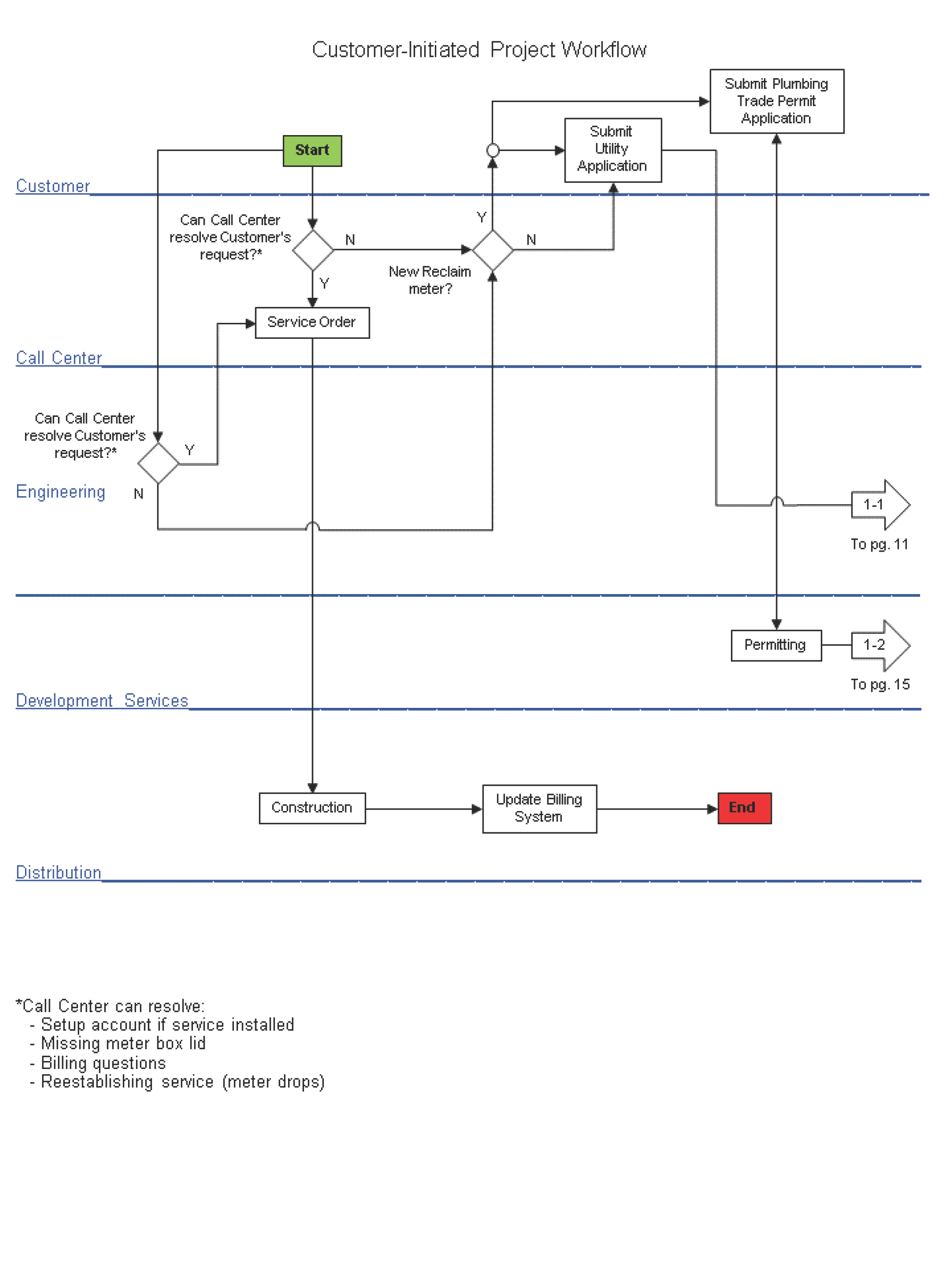
1.1 Generalized Customer-Initiated Project Workflow
The workflow in this section may be superseded at any time by a more recent Tampa Water Department standard.
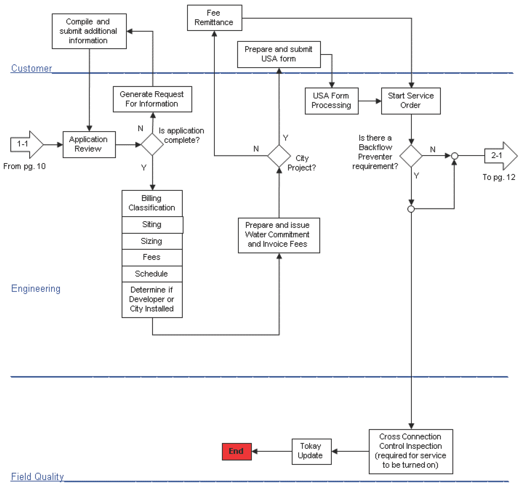
Customer From pg. 10 Compile and submit additional information Application Review Engineering Field Qualit Generate Request For Information Fee Remittance Is application complete? y Billing Classification Siting Sizing Fees Schedule Determine if Developer or City Installed Prepare and submit USA form N y USA Form Processing City Project? Prepare and issue Water Commitment and Invoice Fees Tokay Update Start Service Order Is there a Backflow Preventer requirement? N y Cross Connection Control Inspection (required for service to be turned on) To pg.12
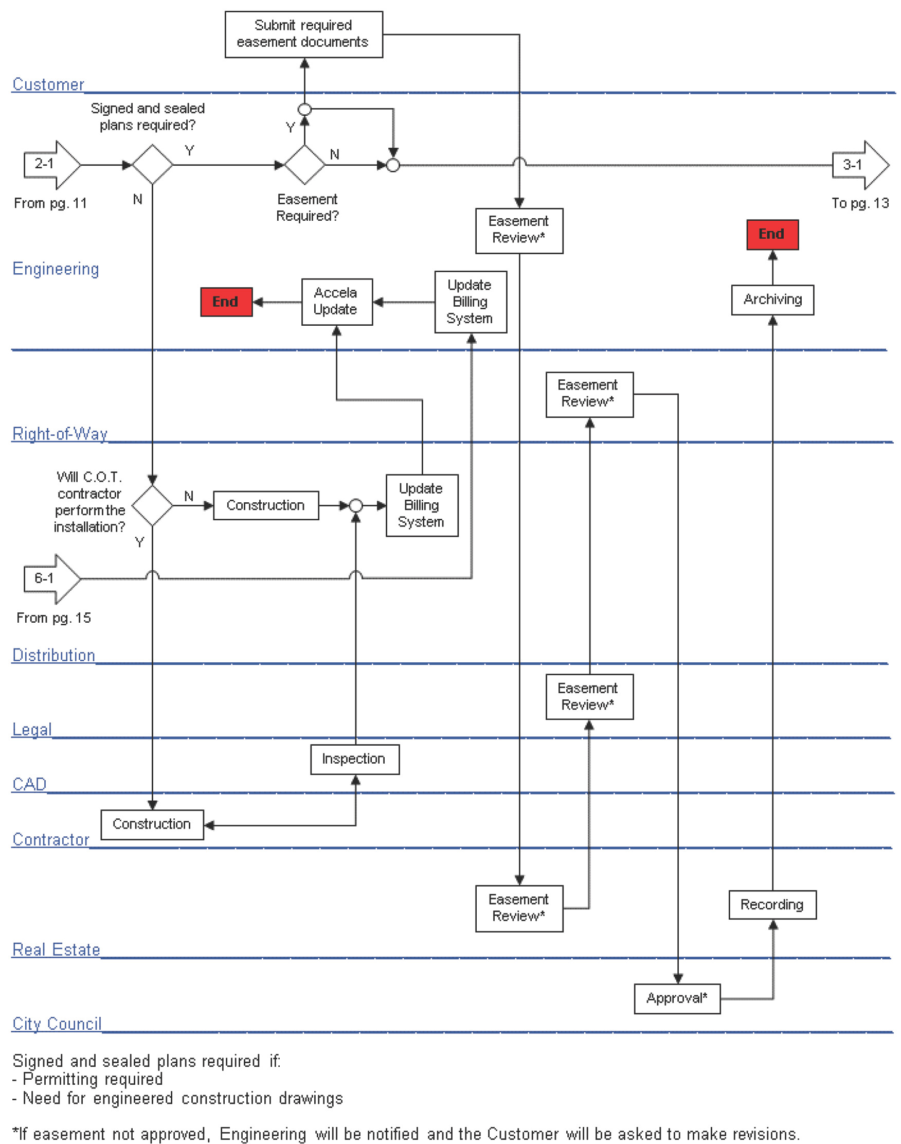
Customer Signed and sealed plans required? From pg.11 Engineering Piaht uf a ill c.o.T. contractor performthe installation? From pg.15 Distribution Legal (AD y N y Construction Ł Contractor Real Estate Cit Council Submit required easement documents N Easement Required? Construction Accela Update Inspection Signed and sealed plans required if: -Permitting required -Need for engineered construction drawings Update Billing System Easement Review* Update Billing System Easement Review* Easement Revienv* Easement Revienv* Archiving Recording Approval* *lf easement not approved, Engineering will be notified and the Customer will be asked to make revisions. 3-1 To pg. 13
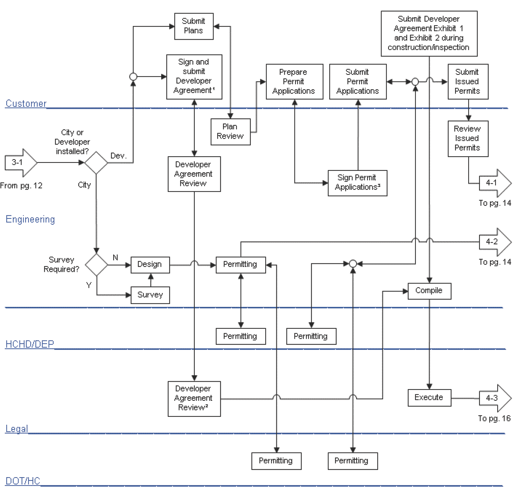
Customer 3-11 From pg. 12 Engineering City or Developer installed? City Survey Required? HCHDDEP Legal DOT/HC Design Survey Submit Plans Sign and submit Developer Agreement2 Developer Agreement Review Developer Agreement Review> Plan Review Permitting Permitting Prepare Permit Applications Permitting Permitting Submit Permit Applications Sign Permit Applications> Permitting Submit Developer Agreement Exhibit 1 and Exhibit 2 during construction inspection Compile Execute Submit Issued Permits Review Issued Permits To pg 14 To pg. 14 To pg. 16
- 1 If required by code or the Water Department.
- 2 If agreement not approved, Engineering will be notified and the Customer will be asked to make revisions.
• The Water Department only signs the available water capacity and ultimate infrastructure owner sections.
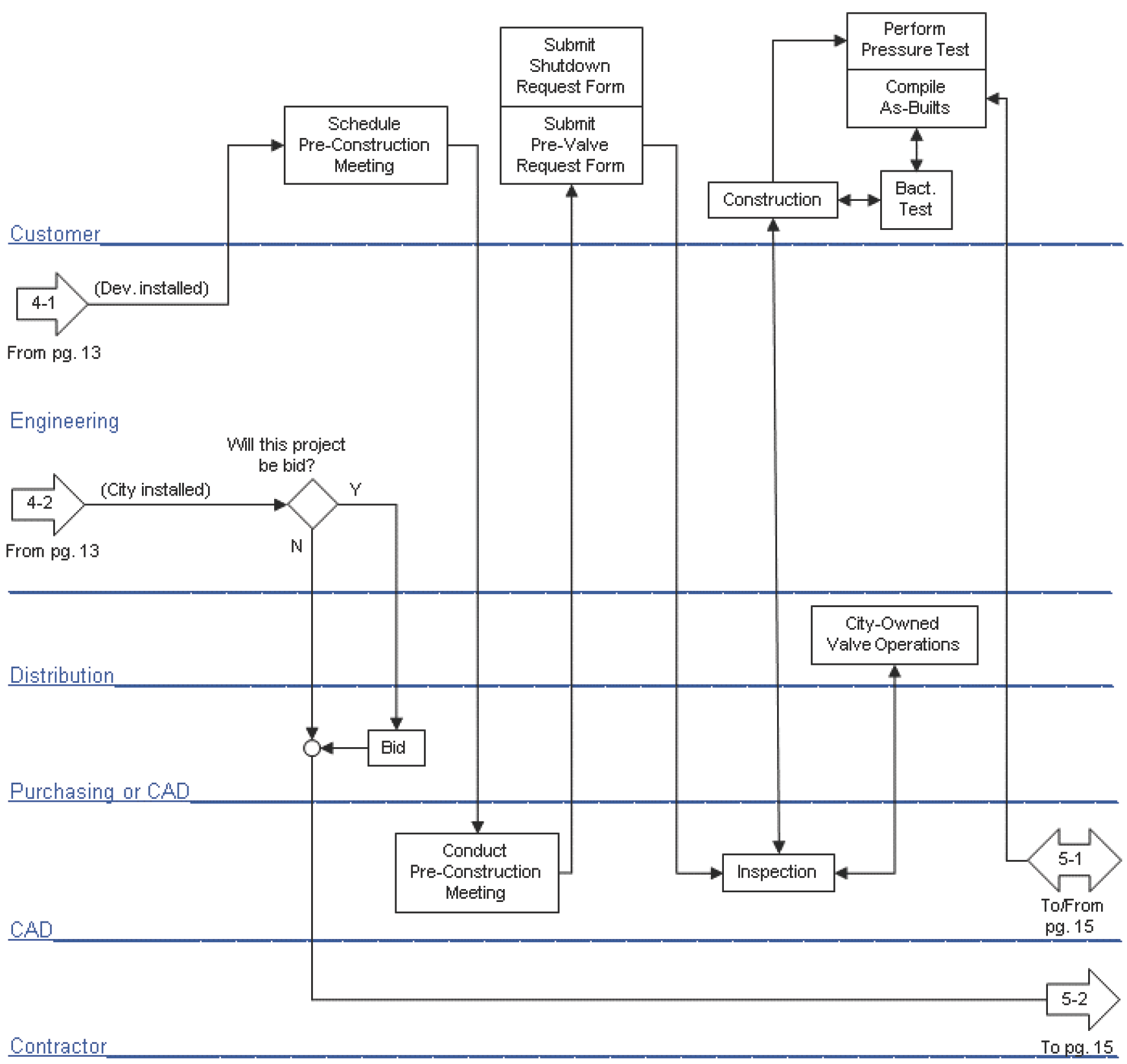
Customer (Dev.installed) From pg. 13 Engineering 4-2 (City installed) From pg.13 Distribution Purchasinc or CAD (AD Contractor Submit Shutdown Request Form Schedule Pre-Construction Meeting Submit Pre-valve Request Form ill this project be bid? N Conduct Pre-Construction Meeting Construction Inspection Perform Pressure Test Compile As-Builts City-Owned Valve Operations To/from pg 15 To .15
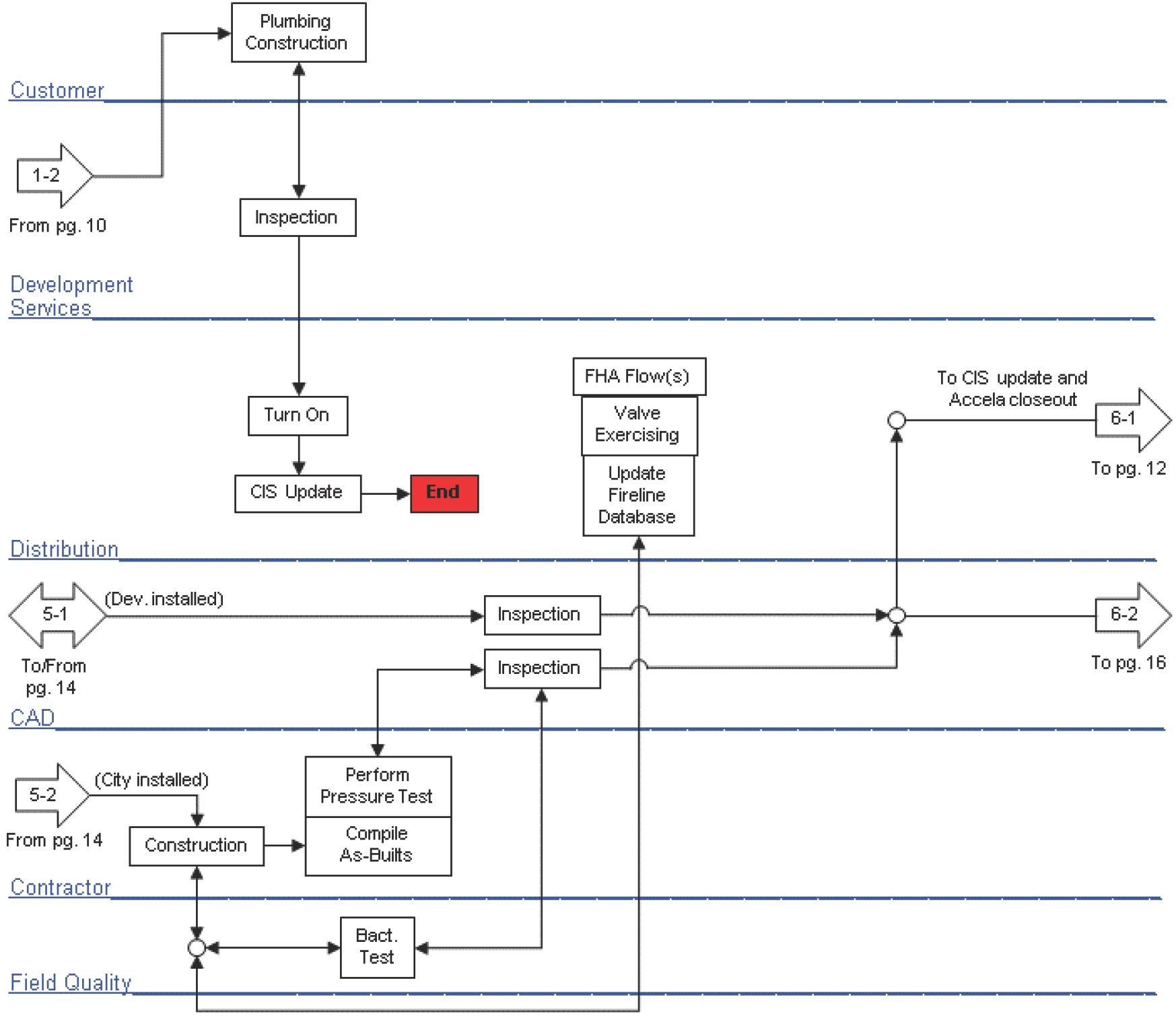
Uustumet From pg.10 Development Se»ices Distribution Plumbing Construction Inspection (Dev installed) MInspection To/From pg.14 CAD 5-2 (City installed) From pg.14 (Contractor Field Oualit Construction rM Inspection Perform Pressure Test Compile As-Buits FHA Flow(s) valve Exercising Update Fireline Database To CIS update and Accela closeout To pg.12 To pg. 16
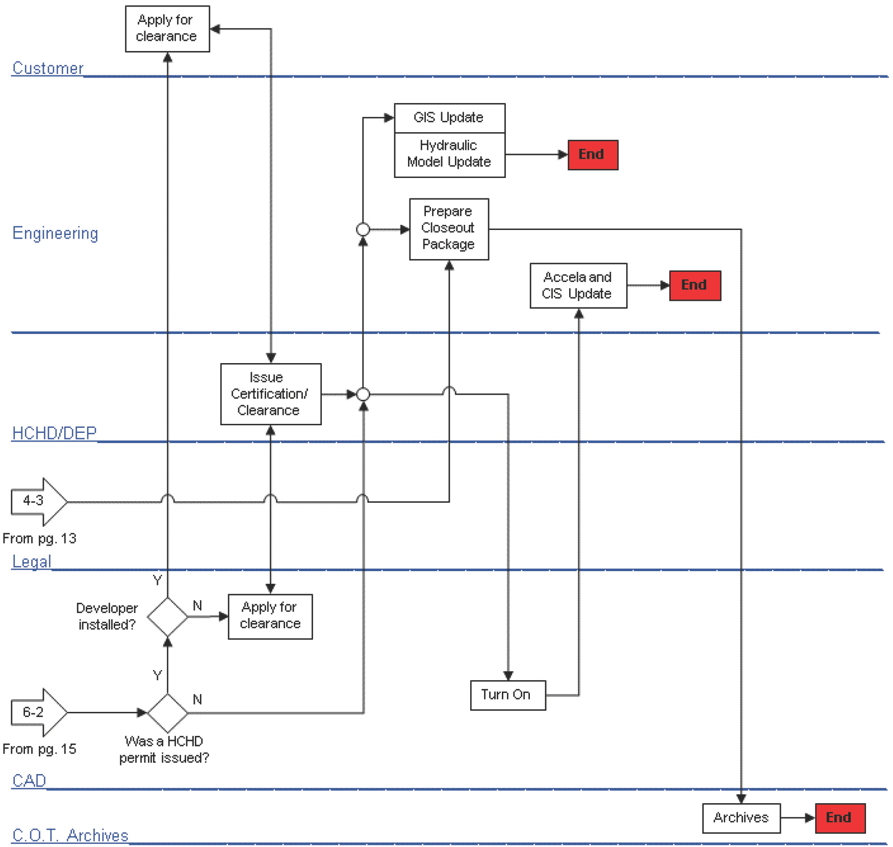
Customer Engineering HCHDDEP 4-3 From pg 13 Leqal Apply for clearance Developer installed? Issue Certification/ Clearance Apply for clearance GIS Update Hydraulic Model Update Prepare Closeout Package Turn On Accela and cIS Update From pg 15 permit issued? C. O.T. Archives Archives
1.2 Water Service Application Requirements
1.2.1 When a Utility Service Application is Required
Each domestic meter and location/address requires a separate utility application.
The following address types may be issued a water service commitment:
- Current Location Point
- Current Master Point
- Current Utility Point
- Current Project Point
- Current Parcel Point
Please contact the Planning and Development Department, Land Development Coordination Division for address related questions.
Residential Projects (Fewer than 3 units)
Listed below are general guidelines for determining when the submittal of a Utility Service Application is required for a residential project.
Residential projects that do require submittal of an application for Water and Wastewater service are as follows:
- Knockdown / Rebuild
- New construction of a residential building
- Private well to City water conversion
- Any activity that needs a new water meter
- Relocation of a water meter
- An existing residential building which has not been associated with an active account for five (5) years or more
- A new fire protection system is proposed OR an existing fire protection system is proposed to be modified; a fire protection system is considered to be modified when an additional area is protected or a greater density of sprinkler heads is to be provided. Maintenance or rehabilitation activities, such as replacing or relocating fire sprinkler heads, is not considered a modification for the purposes of determining if a Utility Service Application is required.
- Installation of an irrigation meter
Residential projects that do not require submittal of a Utility Service Application:
- Renovation / Remodel / Addition
Commercial Projects and Multi-Family Projects (3 or more units)
Listed below are general guidelines for determining when the submittal of a Utility Service Application is required for a commercial project, including multifamily townhomes and condominiums.
Commercial projects that do require submittal of an application for Water and Wastewater service are as follows:
- Construction of a new commercial building(s), including locations where an existing building that previously had water or wastewater service is demolished and a new building is constructed
- Expansion, additions, or interior remodels to existing buildings currently served by a 1-inch water meter or smaller that includes the installation of additional water fixtures
- Expansion, additions, or interior remodels to existing buildings involving a change in use located in a Contribution in Aid of Construction (CIAC) area
- Any project that requires a new or an additional connection or a change to the existing connection to the City’s water or wastewater system
- Expansion, additions, or interior remodels to existing buildings located on a site where there has not been an active water and/or wastewater account within the last five (5) years (regardless of the amount of plumbing involved)
- Interior finish/buildout of a new vacant unit currently connected to the City’s water and/or wastewater system
- Projects that include the construction of public utility infrastructure for either existing or future projects
- Replacement or installation of new pumps in an existing pumping station (only wastewater application required)
- Addition of fire protection system, increase in fire flow demand, or modifications to the existing fire backflow prevention devices.
- Requesting a relocation of the existing meter
- Replacement of water booster pump with a greater capacity
- A new fire protection system is proposed OR an existing fire protection system is proposed to be modified; a fire protection system is considered to be modified when an additional area is protected or a greater density of sprinkler heads is to be provided. Maintenance or rehabilitation activities, such as replacing or relocating fire sprinkler heads, is not considered a modification for the purposes of determining if a Utility Service Application is required.
- Installation of an irrigation meter.
- Installation of a public fire hydrant assembly
- Abandonment / removal of public utility infrastructure
Commercial Projects that do not require submittal of a Utility Service Application:
- Expansion, additions, or interior remodels to existing buildings with no plumbing work
- Interior remodels that involve plumbing, but do not include additional water fixtures. These projects include:
- Replacement of existing plumbing fixtures in-kind
- Relocation of existing fixtures
- Relocation or replacement of plumbing pipes
- Removal of existing plumbing fixtures
- No net increase in plumbing fixtures
- Expansion, additions, or interior remodels to existing buildings that involve plumbing and additional fixtures, but the site is currently served by a 1-½-inch water meter or larger unless the scope of the project is substantial and outside of a typical remodel project
- Projects located on a site served by a private water system (well) and a septic tank; the Developer must provide proof from the County Health Department that the project does not require connections to the City’s water or wastewater system.
1.2.2 Utility Service Application Submittal Guidelines
A Utility Service Application is a joint utility application utilized by both the Water and Wastewater Departments. Utility Service Applications may be submitted online through the City’s permitting website at ACA.TampaGov.Net.
A portable hydrant meter may not be requested through the submittal of a Utility Service Application. Please see Section 1.2.3 for portable hydrant meter guidelines.
Single Family Residential
A Single Family Residential project involves the construction of one (1) residential building.
A Single Family Residential application submittal package must include the following:
- Application Fee
- Utility Plan (if applicable)
- Letter of Authorization for Separate Agent (if applicable)
- Water Customer Data Sheet (if requesting a meter larger than ¾”)
- Fire Flow Data Sheet (if applicable)
- Irrigation Demand Worksheet (if requesting an irrigation meter)
- Water Booster Pump Details (if a booster pump will be installed)
- ERU Calculation Spreadsheet (if within a Contribution in Aid of Construction area)
- Water Meter Placement Diagram
For residential meter installs on undeveloped properties (i.e. where there is nothing on the lot that would be a good reference point for the installation contractor, such as a driveway) please ensure the meter placement diagrams include dimensions from a property corner or some other recognizable landmark to the desired meter location.
Fire Hydrant Assembly
If an existing property owner desires to have a public fire hydrant assembly (FHA) adjacent to their parcel and the public FHA spacing requirements do not currently meet the standards established herein, then an application may be submitted for the installation of a public fire hydrant. The applicant will be responsible for all cost associated with the installation.
A fire hydrant assembly application submittal package must include the following:
- Application Fee
- Water Meter Placement Diagram OR Utility Site Plan
- Letter of Authorization for Separate Agent (if applicable)
The design and installation of the FHA will be performed by either the City or by the Applicant. If the City is to perform the work, the Water Meter Placement Diagram / Utility Site Plan will be used to indicate the desired location of the proposed FHA; however, the City will determine the final location of the FHA.
Interior Build-out
It is common for larger commercial projects involving a collection of smaller commercial spaces, or units, to be constructed as an Infrastructure Only project with the final determination of the use of each unit to be determined at a later time. The use is typically determined by the tenant to occupy the unit. In such cases, only the shell of the buildings or units will be constructed and a subsequent Utility Service Application is required once a tenant is selected.
An application will be required for every Interior Build-out project. If a water meter(s) is installed and fees charged as part of the original Infrastructure Only project, the meter size and fees are an assumption based on the anticipated final use of the unit. The Interior Build-out is application is to confirm the proper fees were collected by the Water Department and as a trigger to set up an account for the new tenant.
An Interior Build-out application submittal package must include the following:
- Application Fee
- Utility Plan
- Letter of Authorization for Separate Agent (if applicable)
- Water Customer Data Sheet
- Fire Flow Data Sheet
- ERU Calculation Spreadsheet (if within a special Contribution in Aid of Construction area)
- Water Meter Placement Diagram (if a new meter is proposed)
Interior Remodel / Minimal Plumbing / No Plumbing
Remodeling projects for existing buildings and projects involving the construction of an addition to an existing building that generates minimal or no change in demand on the Water Department’s distribution system are classified as Interior Remodel / Minimal Plumbing / No Plumbing.
An Interior Remodel / Minimal Plumbing / No Plumbing application submittal package must include the following:
- Application Fee
- Utility Plan
- Letter of Authorization for Separate Agent (if applicable)
- Water Customer Data Sheet
- Fire Flow Data Sheet
- Irrigation Demand Worksheet (if there is an existing or proposed irrigation meter)
- Water Booster Pump Details (if a booster pump will be installed)
- ERU Calculation Spreadsheet (if within a special Contribution in Aid of Construction area)
- Water Meter Placement Diagram (if a new meter is proposed)
Irrigation
Irrigation meters may only be connected to a City potable distribution main if no reclaimed water mains front the parcel.
An Irrigation application submittal package must include the following:
- Application Fee
- Utility Plan
- Letter of Authorization for Separate Agent (if applicable)
- Irrigation Demand Worksheet
- ERU Calculation Spreadsheet (if within a special Contribution in Aid of Construction area)
- Water Meter Placement Diagram
Multi-Family / Non-Residential
A Multi-Family / Non-Residential application submittal package must include the following:
- Application Fee
- Utility Plan
- Letter of Authorization for Separate Agent (if applicable)
- Water Customer Data Sheet
- Fire Flow Data Sheet
- Irrigation Demand Worksheet
- Water Booster Pump Details (if a booster pump will be installed)
- ERU Calculation Spreadsheet (if within a special Contribution in Aid of Construction area)
- Water Meter Placement Diagram
1.2.3 Portable Hydrant Meter Application Submittal Guidelines
At the request of the Developer, the City may install a meter on a fire hydrant assembly. Water service from hydrants is provided to meet needs of a temporary nature, such as construction or other similar needs, as approved by the Director or their designee.
The initial term of service is six months with three-month extensions. Extensions must be requested in writing before the expiration of the current term. Only Water Department personnel are to install, move, or remove temporary meters.
Payment of the appropriate deposit and installation fee in accordance with the latest applicable City Council fee resolution must be made prior to installation or relocation of a portable meter.
The first month’s bill will include any consumption charges and rental fees. If the applicant wishes to have the meter relocated, an email must be sent to PortableHydrantMeter@tampagov.net and a relocation fee will be invoiced on the next month’s bill. The meter may be removed either at the request of the applicant or by the City without notice due to non-compliance by the applicant. The portable meter removal process is as follows:
- Via Request from the Applicant – Mail the request to PortableHydrantMeter@tampagov.net and the meter will be removed. A deposit refund will occur when:
- A written removal request is on file and the meter has been removed, and
- A written deposit refund request has been received by the Water Department, and
- Payment in full of all fees has been received.
- Due to Applicant Non-Compliance – The portable hydrant meter will be removed without notice when:
- The meter is used, for any reason, as a permanent meter to avoid payment of fees for permanent service, or
- No water consumption is registered for a period of three (3) consecutive months, or
- The account is not paid within 30 days of billing date appearing on the statement. The deposit on the account will be applied against the balance due.
Cost of damage to, or loss of, Department equipment will be applied against the deposit and the Department will pursue restitution by the customer of any loss not covered by the deposit.
A Portable Hydrant Meter application package must include the following:
- The completed Portable Hydrant Meter Application
- Initial fee payment as follows:
- A check for the deposit and installation fee, or
- Contact Development Services about other payment methods
- Written permission from the parcel owner to install the portable hydrant meter on an on-site, privately owned, fire hydrant assembly (If applicable)
- A site plan of the project area, if the project encompasses more than a single parcel
1.2.4 Utility Service Application Review
The Department’s Development Services Section staff will review the application. Information that will affect the decision on commitment for water service must be submitted in writing. If the application is incomplete, the applicant will be notified what additional information is needed and provided a date by which information must be received by the Department.
1.2.5 Water Service Commitment Generation and Issuance
If providing water service is physically feasible, financially feasible, and consistent with all Department requirements, a commitment of water service with conditions as appropriate will be issued to the applicant.
1.2.5.1 City vs Developer-Installed Projects
For any project requiring a Utility Service Application, the design, permitting, and construction responsibility for required public water facilities will be determined by the Water Department Director or their designee. Said responsibility will be outlined in the commitment for water service.
If it is determined that the City will perform the design, permitting, and construction of the new public water facilities, the City will be responsible for all associated requirements to provide water service. The responsible party of the project (Applicant, Developer, or Property Owner) will be responsible for all charges and fees associated with the design, permitting, and construction of public water facilities.
If it is determined that the responsible party of the project will perform the design, permitting, and construction of the new public water facilities, then the responsible party of the project will be responsible for all associated requirements to provide water service. It is the responsible party’s responsibility to meet the conditions expressed in the commitment for water service and satisfy design, permitting, and construction requirements as set forth by the Water Department and any other applicable regulatory agencies.
1.2.5.2 Siting
If the parcel for which water service is requested does not abut a dedicated public right-of-way, the water service will be located within public right-of-way. The owner shall provide the Department with evidence of a recorded easement(s) creating a corridor to extend privately owned and maintained piping from said parcel to dedicated public right-of-way. Said easement(s) shall be recorded prior to water service commitment issuance.
Other siting requirements, including easement requirements, will be summarized in the commitment for water service.
1.2.5.2.1 Special Areas
Per City Code, no new private or irrigation wells shall be drilled in an ASR area of influence, the area bounded by W Waters Ave to the North, W Martin Luther King, Jr. Blvd to the South, N Florida Ave to the East, and N Himes Ave to the West.
No use of groundwater or new wells are allowed in the area bounded by E Washington St to the North, Channelside Dr to the East, E Whiting St to the South and N 12th St to the West. RE: Brownsfields Site ID #BF290401001, FDEP Com_233834.
1.2.5.3 Sizing
The commitment for water service will designate required water main, meter, and fireline sizing.
1.2.5.4 Fees
The commitment for water service will identify and serve as the invoice for applicable Water Department fees.
1.2.5.4.1 Application and Review Fees
Application fees do not apply to City of Tampa departments. Application fees apply to all other government entities unless mentioned otherwise herein or are exempted from said fees via law, rule, etc. Customers will be charged an additional application fee if a commitment for water service has been issued and the customer requires a commitment for water service revision, unless the need for the revision was caused by the Water Department.
1.2.5.4.2 Connection Fees
Connection fees are intended to recover the City’s investment in water distribution (excludes transmission, pumping, storage, treatment, water resources) infrastructure less the cost of service connections. Connection fees are established by a City Council Resolution. Common connection fee issues include the following:
- Connection fees apply to all new connections unless specifically stated otherwise herein.
- Connection fees do not apply to the Hillsborough County School Boards; however, they do apply to the Florida Board of Regents.
- Connection fee financing is available for owner-occupied single-family residences within the City and owner-occupied single-family residences existing in unincorporated Hillsborough County prior to October 1, 1997. See City Code for additional details.
- Connection fees are assessed on redundant domestic and / or fire main connections if the customer chooses, or is required, to install redundant service connections.
- Connection fee credits are based on the largest, current connection fee associated with the largest historically installed meter size. Credit may be extended if an existing meter would be inadequate for proposed additions and if a connection fee was originally paid.
- Connection fees are not required for irrigation meters, provided the irrigation meter is not larger than the domestic meter at that location. Irrigation meters at locations without a domestic meter are charged connection fees.
- All new domestic meters serving existing and proposed duplexes will be charged connection fees.
- Strip mall units that are currently master metered and desire to have an individual meter installed will be charged full connection fees regardless of existing master meter size or unused existing meter capacity.
1.2.5.4.3 Service Installation Fees
Customers needing a new or modified service shall be invoiced installation fees as allowed by City Code and / or City Resolutions.
1.2.5.4.4 Abandoned Service Renewals
Abandoned Service Renewals apply to instances where a customer requests water service for a premises, but the previous service has not been active for the below specified time period. In such instances, it is the policy of the Department that the service will be installed after payment, per
City Code, of application and service installation fees. The amount paid will be as set forth in the current fee resolution adopted by City Council.
If a property that has historically been served with City water service has not had an active account for five (5) years, the property will be considered an abandoned water service property, regardless of service size or service type (domestic, irrigation, reclaimed, fire).
If a customer requests water service for an abandoned water service property, the fees associated with re-establishing water service shall include the following:
- If the existing service is consistent with current engineering standards, can be located without excavation, is adequately sized, and is adequately sited for the customer's needs, then the City will install a meter of the same size as pre-existing on the existing service line upon the customer being invoiced the abandoned service renewal fee.
- If the circumstances vary from the above, the fees are as follows:
- If a new service installation would be cost prohibitive (e.g. a long-side set on a 4 lane road, along FDOT right-of-way, or along non-City right-of-way that involves a pavement cut, or similar):
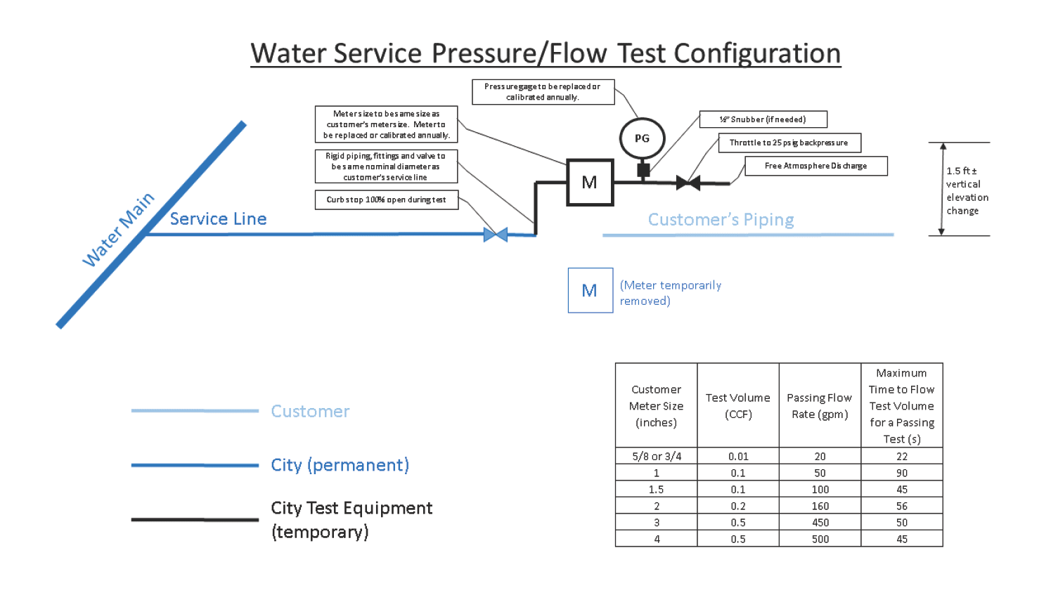
- If the service is in acceptable condition and the service can be located, is adequately sized & sited for the customer's needs, is in acceptable visual condition, and passes a City-performed pressure & flow test, the City will install a meter of the same pre-existing size on the existing service upon the customer’s account being invoiced an abandoned service renewal fee. The pressure and flow tests are defined below.
- If a new service installation would be cost prohibitive (e.g. a long-side set on a 4 lane road, along FDOT right-of-way, or along non-City right-of-way that involves a pavement cut, or similar):
- If the existing service does not meet the aforementioned criteria, a new service will be installed by the City upon the customer paying all applicable water service installation charges. A meter may be temporarily installed on the existing service line, at the Water Department’s discretion, subsequent to the customer paying the water meter installation charges and being invoiced the abandoned service renewal fee, solely for the purposes of reducing the time necessary for the customer to re-establish water service.
All other locations:
- A new service will be installed by the City upon the customer paying all applicable installation charges. A meter may be temporarily installed on an existing service line, at the Water Department’s discretion, subsequent to the customer paying the water meter installation charges and an abandoned service renewal fee, solely for the purposes of reducing the time necessary for the customer to re-establish water service.
1.2.5.4.5 Deposits
Deposits are required per City Code and City Resolution. Deposits do not apply to governmental-type agencies (state, authority, etc.) and fire lines.
1.2.5.4.6 Meter Drop-In Fees
Meter Drop-In Fees apply to Developer-installed water services. If the City installs a meter into a Developer-installed water service and the meter subsequently goes missing prior to the certificate of occupancy, the customer will be charged an additional meter drop-in fee for the City to install a replacement meter.
1.2.5.4.7 Large Meter Furnishing Fees
Customers will be charged the City’s cost of ≥3” meters plus a 25% handling fee.
1.2.5.4.8 City Installation Cost Estimates
When a customer’s water service needs involve any of the below listed circumstances and the construction will be performed by the Water Department, a cost estimate will be generated by the Water Department to satisfy the customer’s water service needs.
- Main extensions, relocations, or upgrades
- Meter ≥3"
- Fire service
- Public Fire hydrant
- Long-side meter installations along four-lane roads
- Work in FDOT or Hillsborough County right-of-way involving a pavement, curb, or sidewalk cut
- Work requiring excavation of pipe having >5' cover based on available as-builts
- Meter service line length greater than 80’
- Meter service line nominal diameter greater than 2”
The customer will then be assessed installation fees consistent with the Water Department’s cost estimate. The Water Department will strive to minimize the customer’s cost while maintaining the Water Department’s technical standards. Customers will not be charged additionally if the cost estimate is less than actual costs. Similarly, partial refunds will not be issued if the cost estimate is higher than actual costs. Cost estimates will include overhead and contingency consistent with the current Department Standard. Cost estimates will include restoration as required by the applicable right-of-way owner.
Water Department installation cost will be determined case-by-case. New growth and development will pay for water main improvements, unless otherwise approved by the Water Department Director. For existing buildings, the main extension should front ten (10) feet of a property. For proposed buildings, the water main should front the entire length of the proposed building’s property, unless there is no expected need to ever extend the water main. For a corner property, the main extension is required only on one side of the property. If a main extension is needed for the customer, a cost estimate will be prepared for installing the water main needed for the customer. The customer will be charged the following:
- Connection fee(s) and
- An aid in construction fee equivalent to the cost estimate value less the connection fee value.
1.2.5.4.9 Aid In Construction Fees
See the City of Tampa Water Department’s Contribution in Aid of Construction (CIAC) policies and the following clarifications:
- The applicant is solely responsible for providing sufficient documentation to provide the Water Department reasonable assurance the claimed historic property usage is accurate. If documentation regarding historic property usage is unavailable, then 15 gpd / 100 square foot of building space may be extended as CIAC credit when there are sufficient records available to show historic building existence and dimensions.
- An irrigation meter installation for a property also served by a domestic meter does not have additional irrigation CIAC fees due because it is assumed irrigation demand is included in the property usage based CIAC fee. If a property is only served by an irrigation meter, CIAC fees apply to the irrigation meter on an equivalent residential unit basis (1 ERU = 300 gpd) based on the customer submitted irrigation demand worksheet.
- Barber & Beauty Shops – if there are 9 total service chairs in the shop as follows:
- 5 chairs for hair cutting / hair styling
- 3 dedicated chairs for hair drying
- 1 dedicated chairs for hair washing
- The Barber/Beauty Shop is considered to have five service chairs.
- Any residential unit having a shared wall with another residential unit are considered multifamily for CIAC fee purposes.
- The daily average water flow factors for a building, structure, or property use are outlined below in order to calculate the equivalent residential unit.
| Connection Type | Gallons per Day |
|---|---|
| Single Family Residential | 300 |
| Multi-Family | |
| Less than 1,600 SF per unit | 150 |
| 1,600 to less than 3,000 SF per unit | 240 |
| 3,000 SF and greater per unit | 300 |
| Airports | |
| Per passenger per day | 4 |
| Add per employee | 15 |
| Barber and Beauty Shops, per chair | 75 |
| Bowling Alley, per lane | 50 |
| Car Wash | |
| Automated, per car | 45 |
| Automated, with water recovery | 8 |
| Self-service, per car | 12 |
| Self-service, with water recovery | 6 |
| Country Clubs | |
| Per resident, or | 100 |
| Per member or patron | 25 |
| Add per employee per 8 hour shift, or | 15 |
| Per member (with showers) | 30 |
| Add per employee per 8 hour shift (with showers) | 25 |
| Apartment/multi-purpose clubhouse per restroom | 250 |
| Doctors and Dentist Offices | |
| Per practitioner | 250 |
| Add per employee per 8 hour shift | 15 |
| Factories, exclusive of Industrial wastes, per employee per 8 hour shift | |
| No showers provided | 15 |
| Showers provided | 25 |
| Flea Market open 3 days or less per week | |
| Per non-food service vendor space | 15 |
| Add per food service establishment using single service articles per 100 SF of floor space | 50 |
| Per limited food service establishment | 25 |
| Flea Market open more than 3 days per week | |
| Per non-food service vendor space | 30 |
| Category | Gallons per Day |
|---|---|
| Add per food service establishment using single service articles per 100 SF of floor space | 100 |
| Per limited food service establishment | 50 |
| Food Service operations | |
| Restaurant open 16 hours or less per day, per seat | 40 |
| Restaurant open more than 16 hours per day, per seat | 60 |
| Restaurant serving single service articles only and open 16 hours or less per day, per seat | 20 |
| Restaurant serving single service articles only and open more than 16 hours per day, per seat | 35 |
| Bar and cocktail lounge per seat | 20 |
| • Add per pool table or video game | 20 |
| Drive-in restaurant, per car space | 15 |
| Carry out only, including caterers | 50 |
| • Add per 100 SF of floor space | 50 |
| • Add per employee per 8 hour shift | 15 |
| Institutions per meal | 5 |
| Food outlets excluding deli, bakery, or meat department per 100 SF of floor space | 10 |
| • Add per deli per 100 SF of floor space | 40 |
| • Add per bakery per 100 SF of floor space | 40 |
| • Add per meat department per 100 SF of floor space | 75 |
| • Add per toilet | 200 |
| Hotels and Motels | |
| Regular, per room | 100 |
| Resort hotels, camps, cottages, per room | 200 |
| Add for self-service laundry, per machine | 750 |
| Laundromats, Launderette, Self-service Laundry facilities, per machine | 260 |
| Trailer Park for recreational vehicles | |
| Per space (overnight) without water and wastewater | 50 |
| Per space (overnight) with water and wastewater | 75 |
| Office buildings | |
| Per employee per 8 hour shift, or | 15 |
| Per 100 SF of floor space, whichever is greater | 15 |
| Recreational / Sports facility, per person | |
| Category | Gallons per day |
|---|---|
| Without showers | 5 |
| With showers | 10 |
| Service Stations / Convenience Store, per toilet | |
| Open 16 hours per day or less | 250 |
| Open more than 16 hours per day | 325 |
| Shopping Centers without food or laundry, per 100 SF of floor space | |
| Stadiums, Arenas, Race Tracks, Ball Parks, per seat | 4 |
| Stores, per 100 SF of floor space | 10 |
| Public swimming and bathing facilities, per person | 10 |
| Theaters and Auditoriums, per seat | 4 |
| Veterinary Clinic | |
| Per practitioner | 250 |
| Add per employee per 8 hour shift | 15 |
| Add per kennel, stall, or cage | 20 |
| Warehouses / Mini-Storage | |
| Per employee per 8 hour shift | 15 |
| Per bathroom | 250 |
| Add for onsite manager apartment | 140 |
| Churches, per seat | 3 |
| Hospitals, per bed | 215 |
| Nursing and Rest Homes, per bed | 115 |
| Parks and public picnic, per person | |
| With toilets only | 5 |
| With bathhouses, showers, and toilets | 10 |
| Public institutions other than Schools and Hospitals, per person (not including kitchen waste flows) | |
| Schools, per student | |
| Day type | 10 |
| • Add for showers | 4 |
| • Add for cafeteria | 4 |
| • Add for day school workers | 15 |
| Boarding type | 75 |
| Daycare | 10 |
| • Add per daycare worker | 15 |
| Work or Construction Camps, semi-permanent, per worker | 50 |
1.2.5.4.10 Capacity Fees
A water capacity fee shall be required for any building, structure, or property receiving water service from the City. The water capacity fee shall be based on the Equivalent Residential Units (ERUs) and location of the building, structure, or property receiving water service and multiplying by the number of ERUs by the water capacity fee for 1 ERU.
The Department shall calculate the net ERUs based on the use of the building, structure, or property and estimated net projected average daily flow. One (1) ERU is equal to 300 gallons per day of average water use for the purpose of calculating the number of ERUs. The daily average water flow factors for a building, structure, or property use are outlined in the table in Section 1.2.5.4.9 of this document.
For a building, structure, or property with previous water service from the City, previous use will be accounted in calculating the net projected daily flow using the flow factors based on previous use. If a property is located within one of the CIAC areas, where CIAC fees are collected for the cost of transmission and storage system components, a reduced water capacity fee that only accounts for the treatment system component shall apply.
In accordance with Section 163.31801, Florida Statutes, the City may provide an exception or waiver for the water capacity fee for the development or construction of housing that is affordable, as defined in Section 420.9071, Florida Statutes. Section 420.9071, Florida Statutes, definition shall be applied to determine if a development is “affordable” to qualify for $0 water capacity fee. It shall be the applicant’s responsibility to provide official documents sufficient to demonstrate that a proposed development qualifies under the Florida Statute definition.
The water capacity fee will be due to the Department prior to the permit issuance. The Department shall withhold approval on the issuance of any site, utility, building, building remodeling, foundation, and/or plumbing permit for a building, structure, or utility appurtenance until the applicable capacity fees are paid.
The water capacity fee, once paid, can’t be transferred or used as a credit or partial payment towards the applicable capacity fee, which may be due and payable for an existing or proposed building, structure, or service connection located on or to be located on a different lot or parcel of land.
The water capacity fees will be reviewed every five (5) years and updated, if determined to be necessary.
1.2.5.4.11 Permit Fees
The City will assess to the customer any 3rd party permit fees to complete the work necessary to serve the applicant. The City does not charge a markup on these fees. Typically, the City only assesses permit fees on certain City-installed projects.
1.2.5.4.12 Inspection Fees
Developer-installed projects will be assessed inspection fees as allowed by the applicable City Council resolution.
1.2.5.4.13 Fire Readiness to Serve Fees
The customer will be assessed an annual fee on all fire services based on the fireline’s nominal diameter.
1.2.5.4.14 Temporary / Construction Service Fees
Water service from hydrants is provided to meet needs of a temporary nature. Payment of the appropriate deposit and installation fee in accordance with the latest applicable City Council resolution must be made prior to installation of the portable meter and delinquency beyond thirty (30) days of the billing date shall be cause for removal of the meter without notice.
1.2.5.4.15 Meter Relocation Fees
Customers requiring their water service to be relocated will be charged fees per the applicable City Council Resolution.
1.2.5.5 Connection Fee Financing
Connection fee financing is available for owner-occupied single-family residences within the City and owner-occupied single-family residences existing in unincorporated Hillsborough County prior to October 1, 1997. See City Code for additional details. A recorded warranty deed is required to verify the name on the utility application matches the property owner. The property appraiser’s website is used to verify the name on the utility application matches the property owner and that the property is homesteaded. The City of Tampa will place a lien on the customer’s property if water connection fees are financed. The 24 month term and 8% interest rate is set by code; however, customers are free to pay off the financed amount at any time within the 24 month term. All other fees such as agreement recording fees, meter installation fees, and application fees must be paid by the customer prior to the meter being installed. The City of Tampa will record a lien release upon receiving final payment.
1.2.5.6 Accepted Payment Forms and Payment Locations
The Tampa Water Department does not accept cash payments or credit card payments via telephone.
Pay By Mail
- Mail a check, payable to “City of Tampa Water Department” and the Water Department project number written in the Note/Comment field, to
City of Tampa Water Department
Attn: Development Services Group
4900 W Lemon Street
Tampa, FL 33609 - Please include your e-mail address and we will e-mail you a copy of your receipt.
Pay by Credit Card On-Line at aca.tampagov.net
- (https://aca.tampagov.net/)aca.tampagov.net
- On the webpage, login using your pre-registered username or e-mail and password. If you have not yet registered, register for an account by clicking the “Register for an Account” link at the top of the page. (Please note that a valid e-mail address is required for registration).
- Once you have registered, you must e-mail us at WaterCommitment@tampagov.net and provide us with the e-mail address used to register for an account.
- We will then link your account to your electronic application and you will be able to pay your commitment fees on-line.
- To pay your commitment fees, click “Search” at the top of the page and select “Building Permits”. Select the Record number corresponding to the address and application number above, navigate down to the “Fees” section, and select “Pay Fees” for any outstanding fees that are listed. Once the fees are paid, an e-mail receipt will automatically be sent to the e-mail address used to register your account.
Pay In-Person by Credit Card or Check
City of Tampa Development Services Center1400 N. Boulevard
Tampa, FL 33607
1.2.5.7 NSF / Insufficient Funds Situations
Upon receipt of a worthless check, all work shall be halted and work orders canceled. In addition to the original amount owed, the customer shall incur the maximum permissible worthless check fee(s).
1.2.5.8 Refunds
Fee refunds are at the Water Department Director’s or their designee’s discretion. Refunds will consider and deduct City resources expended towards accommodating the customer’s request. Connection fees and aid in construction fees are non-refundable upon the customer’s first use of water through their meter.
1.2.5.9 Utility Service Authorization Forms
City-funded projects require the submittal of a Utility Service Authorization (USA) form. The correct funding sources for both the one-time utility fee payments and the monthly utility usage payments shall be indicated on the submitted form. The Water Department’s process for said projects is as follows:
- The City Department requesting water service shall apply for utility service via the online permitting system Accela. Application review fees will be waived to initiate the review process.
- When appropriate, a commitment for water service will be issued and tabulate applicable fees.
- The City Department requesting water service shall generate and submit a USA form to the Water Department. The submitted USA form shall:
- Be signed by the Department requesting service.
- Be signed by the Facility Management Department.
- Indicate the utility application number (“UTL number” generated by the Accela system).
- Include a description of services consistent with the water service commitment letter.
- Include the City funding source for the upfront fees and the monthly charges.
- Upon submitting a completed USA form, the Water Department will begin to install water service or otherwise complete the scope identified in the water service commitment letter.
1.2.5.10 City-Installed Target Time Frames
Target installation schedules for City-installed projects are as follows:
- At least 3-5 working days for small (≤2”) meter installations necessitated by a private well failure if HCHD/HEP/FDOT permitting or main extensions are not required.
- At least 3 weeks for small (<3”) meter installations or relocations having no HCHD/HEP/FDOT permitting.
- At least 3 months for City-installed small meter (<3”) installations that require HCHD/HEP/FDOT permitting.
- At least 8 months for Fire Hydrant Assembly (FHA) installations, FHA relocations, City-installed main extensions, large meters (≥3”) and /or fire mains.
All City-installed installation schedules commence upon water service commitment fees remittance.
1.2.5.11 Cross Connection Control
This manual incorporates the City of Tampa Water Department Cross Connection Control and Backflow Prevention manual via reference, as occasionally amended or revised. Also, refer to the most recent Rules of the Florida Department of Environmental Protection, Table 62-555.360-2: Categories of Customers for Which Each Community Water System (CWS) Shall Ensure Minimum Backflow Protection Is Provided at or for the Service Connection from the CWS to the Customer.
Townhomes are considered residential for cross connection control purposes in the reclaimed area. The Water Department will own and maintain water meters with integral backflow preventers for individually metered townhomes within the reclaimed area. If townhomes in the reclaimed area are master metered, the customer shall own and maintain the backflow preventer (BFP).
Florida Administrative Code requires a dual check device at a residential property connected to reclaimed water service. In an abundance of caution, the Water Department standard for this situation is a double check device to ensure test ports are available for testing.
If a backflow preventer is City-owned, the testing and maintenance of that preventer is done by the Distribution and Consumer Services Division. If a backflow preventer is privately owned, the testing and maintenance is the customer’s responsibility with compliance monitored by the City’s Field Quality Group.
The backflow prevention device and associated assembly shall be upgraded to current FDEP and Water Department standards at the customer’s expense, if:
- The Water Department is providing fire service to a customer utilizing a backflow prevention device inconsistent with standards set by FDEP rule(s) and
- The customer submits a Utility Service Application and pays the resulting water commitment letter fees.
Ownership (unless in conflict with City Code or the applicable water commitment letter):
Separate fire and domestic supply piping with fire backflow prevention or combined fire and domestic supply piping with fire backflow prevention device other than a reduced pressure backflow prevention device:
- All fire service piping, fittings, and appurtenances shall be owned by the Water Department up to, and including, the first valve on the customer side of the fire backflow prevention assembly. The fire backflow prevention assembly consists of two (2) hand wheel valves, a backflow prevention device, and may also include a leakage/theft detector, as shown in Department Standard Details. In the event there is not an isolation valve within the grassed
area or easement on the customer side of the backflow prevention assembly, the Water Department shall own up to:
- The point of customer connection, as shown on available record drawings, or
- The customer side flange face of the backflow prevention assembly.
Combined fire and domestic supply piping with reduced pressure fire backflow prevention device:
- All service piping, fittings, meter(s), and appurtenances shall be owned by the Water Department up to, and including, the downstream flange face of the meter. The reduced pressure backflow prevention device shall be installed on the customer side of this meter.
If no fire main backflow prevention device is installed, the Water Department shall own up to:
- The point of customer connection, as shown on available record drawings, or
- The right-of-way line.
The Water Department shall not own fire main piping, valves, backflow prevention devices, and appurtenances outside of the Water Department’s grassed area or easement unless otherwise stated in the commitment for water service or other comparable document, as determined by the Water Department.
1.2.6 Design
Developer-installed water main construction plans shall be submitted to the Department’s Development Services Section for review (i.e. “plan review”). Plans will be reviewed for conformance with Water Department technical standards. Once the Developer’s plans are determined to be in conformance with Water Department technical standards, the Engineer of Record (EOR) licensed in Florida shall sign and seal the approved plans and submit them to the City’s reviewing engineer. The Department’s stamp of approval (signifying Development Services Section agreement the plans appear to substantially conform to Water Department standards) will be affixed to those plans, and the plans returned to the EOR for use during construction. The Department requires the Developer’s water main Contractor to construct the public water facilities with construction drawings signed and sealed by the EOR and bearing the Water Department’s stamp of approval.
During plan review, if Developer-installed construction plans are determined to not comply with current Department standards and specifications, items requiring revision will be identified through written comments and / or a completed Water Department Construction Drawings Checklist (see Section 2.1.1.5 for current Department Checklist). The checklist lists common technical specifications that must be addressed in the EOR’s construction plans. To expedite plans approval, the EOR is encouraged to review the proposed plans against this checklist prior to submitting for plan review. The Developer’s EOR shall make all required corrections to the plans and submit revised plans for plan review. This process will be repeated until the Developer’s plans are submitted consistent with all technical standards. Plans must be approved within the active timeframe of the governing commitment for water service. If the commitment for water service expires prior to plan approval, the project will be cancelled and fees refunded. Fee refunds will only be sent to the party who submitted the original payment. The Developer must reapply for a new water commitment when ready to proceed with the project.
After receiving notice that the plans are acceptable for construction, the Developer shall submit the following to the Department:
- To be retained for Water Department use:
- Four (4) complete sets of the Developer’s overall project construction plans that include the approved plans for the construction of the City water facilities. Submitting
- “partial plans” (plan sets including only sheets of the Developer’s overall plan set that address the proposed water construction for the City, including any plans showing drainage or sanitary sewers that are impacted by, or will be impacting, the water facilities’ construction) can be discussed with, and may be approved by, the Reviewing Engineer at time of plan approval.
- An electronic copy of the construction plan AutoCAD file(s) approved by the Development Services Section, in .dwg format, or approved equal. Submittal shall include an “Index of Files” identifying applicable City water construction drawings.
- A copy of the applicable permits (FDEP, FDOT, etc).
To be returned to the Developer, for Developer use:
- The number of Department-stamped, approved construction plan sets required by the Developer for distribution and construction. Department specifications require that the Developer’s water main Contractor construct water facilities from plans approved and stamped by the Department, and that a complete set of plans that have been stamped by the Water Department shall be kept on the construction site at all times.
Final Developer construction plans submitted for Department approval (ready to be stamped as approved for construction) must bear the signature, date and seal of the Florida Registered Professional Engineer (the EOR) in responsible charge of the project design. Signing and sealing may be limited to all sheets related to water line construction, including any master utility site plan, individual plan and profile sheets, and any EOR detail sheets. It is not necessary for the EOR to sign and seal the Water Department’s Standard Details.
Construction approval will remain in effect while there is an active commitment for water service for the project.
1.2.7 Third Party Permitting
It is the permittee’s responsibility to ensure all required permits are obtained per applicable regulations. Some regulations pertaining to water main extensions and water service connections are codified in Florida Administrative Code Chapter 62-555, Hillsborough County Ordinance 00-4 and 03-20 and City of Tampa Ordinances Chapter 26.
1.2.7.1 City-Installed
The City will pursue obtaining all required permits.
1.2.7.2 Developer-Installed
The Developer shall obtain all permits necessary to comply with all regulations. Copies of issued permits must be provided prior to the scheduling of a pre-construction meeting with the City’s assigned inspector.
Any permit requiring Department or City signatures must have Department-approved construction drawings.
Developer construction shall not start until all terms of permit comment periods have been met. The waiting period associated with Florida Department of Environmental Protection (FDEP) “Notification for Use of the General Permit for the Construction of an Extension to a Public Drinking Water Distribution System” application and approval process may exceed 30 days. Additional information about FDEP permitting requirements can be found on the FDEP website, at http://www.dep.state.fl.us.
If a FDEP or HCHD Permit is required, no connection to the City’s water system is allowed until the connection has been approved by the Hillsborough County Health Department. After the Developer-installed water facilities have been constructed and tested, the Developer shall apply to FDEP for release of the newly constructed facilities by submitting the “Certification of Construction Completion” and “Request for a Letter of Clearance to Place Public Drinking Water Facility into Service”. Once the release is obtained and has been provided to the Contract Administration Department, the facility may be connected to the City’s water system without everyday use of water. Until ownership has been transferred to the City of Tampa, valves will be closed and meters locked until all requirements have been met, including a backflow preventer inspection by the Department’s Cross Connection Control Section. Exception is allowed to this “locked meter” requirement if the Developer-installed project is for providing water service to single family residences which do not require backflow prevention devices.
Before submitting the application form to the Department for City sign-off, the Developer should review the City data to ensure that it is the most current as of the date of the submittal.
1.2.8 Construction
Approved construction plans will be forwarded to the City’s Contract Administration Department to facilitate the required coordination among the Developer, Contractor, Inspector, and Construction Engineer. The Developer and/or their representatives shall use the project number (e.g. UTL-yy-zzzzzz) to reference the project in all communication.
A pre-construction meeting will not be permitted until five (5) working days after any applicable required permits have been issued from the Hillsborough County Health Department and / or the Florida Department of Transportation have been received by the Water Department. During this contact, the Developer’s representative shall provide an e-mail address to which Department-required forms can be sent for Developer use, including several forms which must be completed by the Contractor prior to the Pre-Construction meeting.
1.2.8.1 Material Submittals and Pre-Construction Meeting
The Developer’s EOR shall submit five (5) completed and signed copies of the current Water Department “Approved Materials List” submittal form to the Water Department Contract Administration Department office.
The Approved Materials List identifies various manufacturers and products that have been previously approved by the Water Department. If Developer-proposed pipes, fittings, valves, hydrants, and other pipe appurtenances are listed therein, the Approved Materials List submittal form will be the only submittal required by the Contract Administration Department for review and acceptance of the Contractor-provided materials. The current Approved Materials List submittal form is available from the Contract Administration Department office and will be e-mailed to the address provided by the Contractor when arrangements are made for the pre-construction meeting.
Contractors proposing to install products not included in the Approved Materials List must submit material certifications and shop-drawings for those non-listed materials to the Department for review and approval to:
Contract Administration Department3808 E. 26th Avenue
Tampa, FL 33605
ATTN: Chief Construction Engineer
Developer-proposed materials requiring submittal for approval include, but are not necessarily limited to, the following:
- Pipe
- Fittings
- Valves
- Hydrants
- Service lines
- Restraint devices
Other materials may require submittal, as determined by the Chief Construction Engineer.
Five (5) originals of a material submittal are required and each must bear a signed, sealed, and dated (Florida P.E.) statement attesting to conformance with the Department’s specifications. The submittal forms must be hand-delivered or mailed to the Contract Administration Department. Faxed submittals will not be accepted.
After approval of the Developer’s proposed water main construction materials, the Developer’s representative shall schedule the mandatory pre-construction meeting with the Contract Administration Department. All parties responsible for the Developer-installed construction, and the final transfer of those facilities to the City after construction, shall attend the meeting, including but not limited to the construction P.E., the Contractor, and the Developer or their representative.
Developer-installed water main construction may not begin until materials are approved by the Contract Administration Department, the Pre-Construction meeting has been held, the Contractor-provided materials have been inspected by CAD, and the Pre-Valve and Shutdown Request forms have been submitted. These forms shall be available to the Contractor from the assigned City inspector.
Under no circumstances shall contractors tap or connect to a City of Tampa water main without written authorization from the Department’s Construction Engineer.
Any Developer-installed water facilities constructed prior to materials approval, materials inspection, and the pre-construction meeting are subject to Developer removal and replacement at the discretion and direction of the Water Department, at no cost to the City.
1.2.8.2 Hydrostatic and Bacteriological Tests
The Developer shall be responsible for performing City Inspector witnessed hydrostatic and bacteriological tests, per section 2.2.7.2 of this document, for all Developer-installed projects.
1.2.8.3 Clearance Application
The Developer is responsible for submitting DEP/DOH clearance applications, as applicable, for Developer-installed projects.
1.2.9 Developer Agreements
All Developer-installed projects require the execution of TWD’s standard Developer Agreement prior to CO holds being released. There are seven (7) different forms for this agreement depending on the type of entity involved (corporate, individual, two individuals, joint venture, LLC, partnership, and special entity). The Customer is required to submit three (3) original, signed agreements for City processing. The submittal shall include Exhibit I “Engineer of Record Certification of Materials” and Exhibit II “Engineer of Record Certification of Construction Costs.” Customers are encouraged to submit these documents for City execution as soon as possible to prevent CO issuance delays.
1.2.10 Project Closeout
1.2.10.1 Record Drawings
Purpose: The purpose of this section is to establish as-built data collection standards for the water pipe networks. These standards shall be met for all Developer-installed water main extensions, relocations or replacement.
Definitions:
- As-Built – Revised set of drawings submitted upon project completion reflecting all changes made in the specifications and drawings during the construction process and showing the exact dimensions, geometry, and location of all elements of the work completed.
- HDD – Horizontal Directional Drilling (HDD) is a minimal impact, trenchless method of installing underground pipe, conduit, or cables in a relatively shallow arc or radius along a prescribed underground bore path by using a surface-launched drilling rig.
- Coordinates – x, y, and z coordinates.
- Limits of Pipe – The beginning and ending points of a pipe where it may or may not connect to the TWD water system.
During construction, installation, and testing, records shall be created and maintained of all work performed.
The Contractor shall provide TWD with:
- One (1) unlocked AutoCAD (Civil 3D preferred) drawing electronic file (.dwg format) with an updated and accurate pipe network(s) that depicts final field conditions, and
- One (1) signed and one (1) unsigned electronic copy in Portable Document Format (PDF) of the as-built drawing.
The as-built shall be signed and sealed by a Florida registered Surveyor and a Florida registered Professional Engineer (digitally signed and sealed is acceptable). The paper size shall be “11x17.”
AutoCAD drawing requirements:
- The as-built shall be geo-referenced to the Florida State Plane Coordinate System, Traverse Mercator, West Zone of 1983 in feet (NAD 83-90 FT). All vertical elevations shall be referenced to the North American Vertical Datum of 1988 (NAVD88).
- All x, y, and z coordinates will be shown to 0.xx’ accuracy on the As-Builts.
The Consultant / Contractor / Developer is responsible for, and shall verify, the AutoCAD version to be utilized with the Water Department’s Drafting Supervisor prior to starting the record drawings’ survey.
The as-built shall indicate pipe size and material. It also shall include the x, y, and z coordinates (Easting(x), Northing(y), Elevation(z)) at:
- All water fittings
- Water meter services (corporation stop, center of meter box top, center of housekeeping pad if applicable)
- The operating nut of all valves and hydrants
- Top of pipe for one side, where the pipe goes into each valve bell
- Top center of pipe at no greater than every fifty (50) feet along all water pipelines (transmission and distribution) including the beginning and ending connection points to the TWD water system
- Top center of the casing ends for pipes installed via Jack and Bore construction method
- Top center of the pipe at all excavated locations for pipes installed via pipe bursting
- Top center of the pipe at the limits and all excavated locations of the abandoned pipe
- Method of abandonment
- The pipe locations as contained in the bore log for pipes installed via HDD and the bore log
1.2.10.2 Closeout Checklist
Upon completion of the Developer-installed water main construction, the installations must be field accepted and finalized by the assigned Contract Administration Department inspector. Any meters served from Developer-installed water mains will not be released to the Developer until the following have been provided complete to, and accepted by, the Contract Administration Department:
- Two (2) sets of as-built construction plans, per Section 1.2.9.1 Record Drawings
- One (1) “Construction Costs” form completed, signed, and sealed by the Engineer of Record
- Two (2) copies of the bacteriological (Bac T) samples report, one for City records and one for transmittal with the Hillsborough County Health Department clearance forms. Bacteriological samples reported cannot be over 60 days old and must have been processed with appropriate chain-of-custody documentation by a City of Tampa approved lab (samples hand-carried to the lab by persons other than laboratory personnel will not be accepted). The name and telephone numbers of the lab the Contractor proposes to use for bacteriological sampling and testing shall be provided to the Water Department inspector at the pre-construction meeting.
- Completed DEP Clearance Application Form, ready for required sign-off by the Contract Administration Department’s Chief Construction Engineer. After said sign-off on the form, the Developer shall forward the application form and documentation to the Health Department for DEP project close-out.
- Three (3) sets of completed City of Tampa Developer Agreements, all bearing original signatures
The referenced forms are available from the Contract Administration Department. Because it is a violation of State Statute for the City of Tampa to provide water service to customers from new water mains without final clearance from the Department of Environmental Protection, no meters will be provided to customers until the required documents are provided and accepted.
A sample Health Department clearance form will be provided by the Contract Administration Department at the Pre-Construction Meeting containing specific City of Tampa information required for the Developer to complete the form. The sample form is also available electronically from the Contract Administration Department.
Sign-off by the Water Department is required on Developer Health Department clearance forms for Developer-installed water facilities. The Department’s Chief Construction Engineer will not sign-off on the clearance form until all other required paperwork has been accepted and approved by the Contract Administration Department. Developers shall fax or e-mail the DEP clearance to the Contract Administration Department.
1.3 Plat and / or Master Planned Developments
State and local law governs how property is divided. Dividing property is accomplished via the platting process. State law dictates that if a property is divided into three or more parcels, it must be done via the platting process. Platting is an administrative process defined by State Law and City Code. The platting process can’t modify a City technical standard or City Code. Final plats must be approved by City Council. The primary goal of the platting process is to ensure public services are available to each created parcel.
Final plats cannot be approved without utilities being readily available or a bond is posted for 125% of the estimated cost to construct the utilities. The respective utility department determines if this bond value is adequate. Ninety (90) percent of the bond value is released when the Water Department Developer Agreement is executed. This transfers infrastructure ownership and starts a thirteen (13) month warranty period. The remaining 10% of the bond value is released after the thirteen (13) month warranty period has elapsed.
There are two types of legal descriptions:
- Platted – reads like “Lot 1 of ‘ABC’ Subdivision”
- Metes and Bounds (has never been platted) – reads like “From the P.O.B., N13 degrees W 100 feet, etc.”
Approved preliminary plats are not required to be approved by City Council; however, they are binding for zoning and permitting purposes. The City only requires preliminary plat approval if a new roadway is involved.
1.3.1 Preliminary Plat Requirements
Water Department requirements for preliminary plat approval include the following:
- A complete utility application has been submitted.
- The right-of-way is sufficient for installation of water systems.
- The easement locations, dimensions, and dedication language are acceptable.
- The right-of-way is delineated as public or private.
1.3.2 Final Plat Requirements
Water Department requirements for final plat approval include the following:
- A water service commitment has been issued.
- Construction plans are approved.
- Easements are delineated and dedication language is sufficient.
- The easement is consistent with the approved construction plans.
- Certified cost estimate or bid received and approved (to determine bond value).
- The performance bond required for improvements is completed prior to City Council review of plat.
- The warranty bond required for public improvements is not completed prior to City Council review of plat.
- Infrastructure construction is complete or bond is posted and infrastructure plans are approved.
Easements for water utility needs can be dedicated via the platting process.
The Water Department requires one application, one commitment letter, and one work order number per project phase. Provided the entire bond value remains effective until all water-related work for all phases included in the final plat are complete, the Water Department has no objection to a final plat including more than one project phase.
1.3.3 Community Master Plan Requirements
1.3.3.1 Components
Customers are required to submit the following for master planned developments:
- A separate utility application for each project phase
- A project narrative describing the entire project and identifying anticipated project phasing
- Hydraulic model file submittal and report
- Phasing plan and anticipated schedule
- Map indicating phases and boundaries
1.3.3.2 Phasing
All phases must function independently if they are to be constructed out of order (i.e. Phase 1 must independently meet Water Department standards if Phase 2 is to be constructed afterwards). Each phase must be applied for independently if they are to be constructed at different times.
1.3.3.3 Hydraulic Modeling
The City utilizes hydraulic modeling software to verify all Community Master Plan water main sizing is consistent with Water Department technical standards. Approval of sizing and layout is at the Water Department’s discretion. Upon the City receiving average day, maximum day, and peak hour flow demands from the Developer, the City will provide the feed pressure to be assumed at each development connection point. The Customer shall submit the hydraulic model files in EPANET .inp format and a report indicating modeled results including the following:
- Minimum 40 psi in distribution mains (non-fire flow conditions)
- Minimum 50 psi in transmission mains (non-fire flow conditions)
- >25 psig residual pressure at 1,000 gpm fire flow (residential)
- >25 psig residual pressure at 3,500 gpm fire flow (commercial and industrial)
- Pipe list indicating diameter, length, C-Factor, and velocity (peak hour and max day + fire flow condition)
C-Factors shall be assumed as follows:
| Pipe Material | C-Factor |
|---|---|
| Ductile Iron | 140 |
- Node list indicating elevation, demand, residual pressure at 1,000 gpm fire flow during maximum day demands (residential), residual pressure at 3,500 gpm fire flow during maximum day demands (commercial and industrial), average day pressure, maximum day pressure, peak hour pressure, and water age
1.4 Right-of-Way Vacates, Right-of-Way Encroachments, and Easement Releases
The Water Department will approve, at its sole discretion, right-of-way vacates, right-of-way encroachments, and easement releases provided said petitions will not compromise the Water Department’s ability to economically provide water service to its customers. During the Water Department’s review, if it is determined that work on the public water system is required to approve a petition, the following Water Department process is utilized prior to approval:
- Customer submits an application for utility service
- Customer pays the resulting commitment fees (if applicable)
- The Developer’s engineer submits signed engineered plans for Water Department Engineering Section’s approval (if applicable)
- The Developer’s Contractor performs the work outlined in the commitment, under observation of a City inspector (if applicable)
- The Developer’s engineer submits as-built plans
- City of Tampa accepts the work
1.5 Demolition Permits
If demolishing any structure on their property, the property owner shall complete a Demolition Permit application through the City’s online application service.
1.6 Rezoning
The Water Department will perform a cursory review of proposed zoning changes and may provide comments pertaining to anticipated Water Department requirements.
1.7 Comprehensive Plan Amendments
The Water Department will perform a cursory review of proposed comprehensive plan amendments and may provide comments pertaining to anticipated Water Department requirements.
1.8 Food Truck Approvals
Upon a customer’s request, the Water Department’s Development Services Section will review “Interagency Coordination of Regulated Establishments – DOH/DACS/DBPR/DCF/AHCA/APD Evaluation of Onsite Sewage (Septic) and Water Supply Capacity” forms. The Water Department will provide its approval on said form if the applicant is a Tampa Water Department customer with adequate water service.
1.9 Requesting As-Builts
Requests for atlas or as-built information may be emailed directly to watermapsandasbuilts@tampagov.net.
1.10 Requesting Fire Hydrant Flow Tests
Those requesting publicly-owned fire hydrant flow test information can do so by emailing the Water Department Planning Section at watercommitment@tampagov.net. Please provide the following information within the email:
- Requester’s name
- Company
- Phone
- Fax
- Location of fire hydrant(s)
If existing hydrant flow test information is not adequate, often due to the test date, a new test will be ordered. Static pressure, residual pressure, and measured flow will be provided to the Customer. Any additional assumptions or calculations will be the responsibility of the requester.
1.11 Building Permit Holds
Whenever one of the following building permit record types is submitted, three Water Department Holds are automatically applied to the building permit:
- Residential New Construction & Additions
- Commercial New Construction & Additions
- Commercial Building Alteration
These holds, and what releases them, are as follows:
- Utility Application required
- Released when the Water Department or Wastewater Department accepts the Utility Application
- Water Commitment required
- Released when the Water Department determines no further action is required on its part or when the Customer pays all water commitment fees
- Water Certificate of Occupancy Hold
- Released when the Water Department confirms all construction work and associated submittals are complete (including easement acquisition documents) and all water commitment fees have been paid
1.12 Easement Acquisition
If the Water Department determines that public water facilities must be located on private property, an easement may be required to be dedicated to the City as determined by the Water Department. The size and location of the facilities will be determined at the time of application for utility service. The public facilities must be centered within the easement. The installation of permanent structures, pavement, impervious surface material, or landscaping will not be permitted within, on, over, or under the referenced easement without prior review and approval of the Water Department. In the event the public facilities located within the referenced easement need to be accessed and / or excavated, the City shall only be responsible for returning the excavated areas to finish grade and restoring any pavement that is disturbed to the quality of pavement that meets the minimum standard for public streets in the City of Tampa.
The following information and items must be submitted to the Water Department in order for the City to prepare the easement dedication:
- A title commitment covering the entire parent tract of the project/development which shows the ownership, legal description, and all encumbrances affecting the property, including copies of all easements of record. The title commitment must be submitted to the Department within 30 days of completion. An Ownership and Encumbrances Report shall not be accepted. For questions regarding City standards for title commitments, please contact the City’s Real Estate Division.
- A Grant of Water Easement deed, consistent with the City’s standards, must be signed and attested to by the property ownership officers, and must convey the easement interest to the “CITY OF TAMPA”. Please leave the date blank on the first page. The portions of the deed to be filled out on the third page are: Witnesses (Two (2) required), Name (as specifically stated in the Title Commitment and/or the Title Policy) and Notary. The easement must be accompanied by any mortgage subordinations, releases, or other legal instruments needed to convey the easement to the City free and clear of all encumbrances. The City of Tampa will record this document. For questions regarding City standards for Grant of Water Easement deeds, please contact the City’s Real Estate Division.
- Three (3) copies of the easement boundary sketches on 8-½” X 11” sheets and an electronic AutoCAD file with the easement boundary sketch. The boundary sketch must include a sketch of the parent tract and easement, along with legal descriptions of both, and must be sealed by a registered Land Surveyor. The proposed easement must be labeled as “Water Easement” and not “Utility Easement”. For questions regarding City standards for boundary sketches, please contact the City’s Right of Way and Mapping Section.
- A Joinder and Consent, consistent with the City’s standards, signed by the Mortgage holder if a lien is outstanding against the property.
If the Grant of Water Easement deed is altered in any way, the submittals will not be accepted, and the proper documents must be resubmitted. A certificate of occupancy hold will be placed on any project requiring an easement to be dedicated to the City of Tampa and will not be released until all information required for the dedication of the easement is received and approved for accuracy.
2.0 Material, Workmanship, and Other Specifications
Nothing in this manual may be construed to disallow the City from pursuing alternate design criteria and/or material standards for City-installed projects.
2.1 Drafting
This section lists general drafting requirements for plans submitted to the Department for review and approval. Since each project may have conditions specific to that project which may affect construction complexity, there may be additional requirements not listed in this section.
All plans submitted to the Department for approval must bear the signature, date, and stamped seal of the Florida Registered Professional Engineer responsible for the project.
2.1.1 General
2.1.1.1 Drawing Size
All water main construction plans shall be on 11" x 17" sheets.
2.1.1.2 Drawing Scales
For all construction plans, the horizontal scale shall be 1'' = 20', or 30', or 40', or 50' and the corresponding vertical scale shall be 1'' = 2', or 3', or 4', or 5'.
If call-outs or proposed water facility design are not legible due to Developer’s use of smaller scale, at the discretion of the Department’s Engineer reviewing the Developer’s plans, a detail with larger scale will be required.
A plan-view of the site indicating locations of existing and proposed utilities, including labels for the property corners and limits of the rights-of-way, shall be provided in a minimum 1'' = 100' scale. On large projects, 1'' = 200' scale will be allowed.
The cover sheet of the plans shall include a vicinity map clearly indicating the location of the proposed construction.
2.1.1.3 Plan and Profile Views
- The profile-view shall be shown directly below the plan-view with cross sections shown where necessary.
- Plan-view details shall emphasize the correct location of existing and proposed utilities. Property corners and iron pins shall be shown to identify the limits of the right-of-way. Each “Water Construction” plan-view sheet shall have the nearest benchmark indicated by note or call-out.
- Profile-views shall show all utilities crossing the proposed water main and all parallel utilities within 10 feet of the proposed water main. Water main minimum depth of cover required shall be clearly labeled in the profile-views and in any cross-section views provided.
- Adequate horizontal and vertical control shall be shown on each plan sheet.
2.1.1.4 Survey and State Plane Requirements
Refer to Section 1.2.10.1 of this document for datum requirements.
2.1.1.5 Construction Drawing Checklist
A checklist is used by the Water Department when reviewing Developer-prepared construction plans for conformance with technical standards. The checklist is not intended to be inclusive of all Water Department technical standards. The checklist serves as an outline for the Department’s review of Developer-prepared plans. Water Department checklists are included in the below subsections.
2.1.1.5.1 Pipeline
- Does the proposed water main have sufficient clearance from other utilities, based on Hillsborough County Health Department and City of Tampa standards?
- Are crossing utilities shown in the profile and/or cross section views?
- Are invert and/or top elevations of all intersecting utilities in the profile view specified?
- Is the required minimum pipe cover specified in each profile or cross-section?
- Whenever the water line route crosses existing pavement, is the method of crossing shown on the plans and specified, i.e., jack-and-bore, open cut, etc.?
- Do jack-and-bore casings extend to at least 8-feet beyond the edge of pavement in FDOT or 4-feet in Hillsborough County rights-of-way?
- If a jack-and-bore is planned, is a cross-sectional detail of the jacking operation included, and is it in accordance with the appropriate Department Standard Detail? Is casing pipe diameter, class, and thickness labeled in the profile view?
- For ductile iron pipe, is the maximum allowable deflection in degrees per joint noted on the water plan sheets, and are station and offset of the BEGINNING and ENDING of required pipe joint deflections called out?
- Is note or call-out included on the City water construction plan sheet that “All DIP water mains and fittings shall be polywrapped per TWD Standard Detail 2.05”? Current Department specifications require that all ductile iron pipe and fittings be wrapped in polyethylene encasement, in accordance with Detail 2.05.
- Are the size and type of pipe shown for all existing and proposed water mains?
- Are size and type of pipe consistent with Department requirements?
- Are all necessary pipes shown?
- Is ductile iron pipe (only) used under collector or arterial roads?
- Is the appropriate “Restraint Length” table included in the plan Detail Sheets?
- Are all trees and roots within the limits of the pipeline trench designated for removal and disposal? Are proposed tree plantings at least 10 feet from the water main?
- Is the appropriate separation shown between metal gas lines and water mains?
- Are “sample taps” shown on all mainlines, spaced at distances not exceeding 1,200 feet, at the end of all dead-end lines, and at the end of all branch runs? Are “chlorine injection points” labeled?
- Is all dimensioning in compliance with applicable permitting agency’s requirements?
- Are call-outs provided at crossings where a water main crosses under storm or sanitary sewer pipes “Center 18 LF of jointless water pipe at the crossing” and “12-inch min” separation whenever
2.1.1.5.2 General Requirements
- On each design sheet for City water installations, is horizontal control (distances to at least three permanent landmarks and/or to centers of the nearest intersection(s)) and vertical control (via permanent or temporary benchmarks) included to locate where the City water facilities are to be constructed? If required, is stationing correct?
- Are survey markers and benchmarks, as well as any other necessary horizontal and vertical control, shown and identified?
- Are match lines required? Are they identified and stationed properly?
- Are widths of pavement, curbs, driveways, and sidewalks shown?
- Is a location map shown? Is the proper location identified as "Project Location"?
- Are widths of all rights-of-way labeled on all streets?
- Is there a profile shown directly below the plan view for the proposed water main and/or are cross sections shown where necessary?
- Are proposed grade and existing grade shown over the proposed water main?
- Are all existing and proposed utilities shown and located?
- Are all existing and proposed trees within 10-feet of the water main shown and is clearance between the proposed water main and those trees adequate?
- Have the plans been signed and sealed by the Registered Professional Engineer responsible for this project?
- Are all street names properly shown and clearly labeled?
- If the water plan sheet(s) include any un-named streets that are not yet platted, does plan include note that: “Permanent street names will be provided on as-builts”.
- Is the north arrow shown on all sheets properly?
- Is proper drawing scale shown, and are plans drawn to scale?
- Are all symbols and linetypes shown in plan-view in agreement with the legend?
- If an easement is required, is it properly shown and identified (location, dimensions, and labels)? If a “grassed area” only is required, is it likewise shown and labeled: “X’ x X’ Clear Grassed Area for City Water Department Access”.
- Are all necessary Department Standard Details, specific to the water facilities to be Developer-installed for the City, included in the plan Detail Sheets? Are the Standard Details included current versions and are they unaltered?
- Are there any additional or special notes to be added to the plans that are stated on the Checklist “Comments Sheet”, as provided by the Department during the Construction Plan Review?
- Is a “revisions box” included on each sheet of the plans and is it accordingly marked and dated as revisions are made to the plans? Does the “revisions box” include date, revision description, Department revision was made for (if revised per City of Tampa comments), and the initials of person who revised the plans?
2.1.1.5.3 Valves, Fittings, Taps
- Are all valves, fittings and bends shown, labeled, and stationed on the plan for horizontal bends or profile for vertical bends?
- Are the proper number, location, and type of valves provided?
- Are valve boxes called out for each valve to be installed?
- Are bends and offsets minimized?
- Are restrained joint lengths and locations properly calculated and then labeled in the profile-view,
2.1.1.5.4 Hydrants and Meter Services
- Are hydrant assemblies properly drawn and labeled (including appropriate tee, gate valve and a call-out for the valve box) and proper installation methods called out?
- Are fire hydrants provided as required to meet Department requirements?
- Are fire hydrant bottom flange elevations set at proper elevation and distance from curb? Are flange elevations calculated based on proposed finish grade at the hydrant and labeled in plan profile view?
- Are all proposed meter service lines shown which run under pavement and is sizing consistent with Department requirements?
- For long-side meter services, are casings shown and accordingly labeled?
- Are meter service line connections to water mains shown correctly and in accordance with the applicable Department Standard Detail? Is there a call-out for the correct type/size of connection, the service line, and the meter(s)? Is call-out included for the connection between service line and water main “Service line connection to water main”, per TWD Standard Detail 5.01?
2.2 Design Standards
2.2.1 General
This section of the manual highlights many of the design standards utilized and required by the Department. This section is not intended to be all-encompassing of Department design standards, but rather to serve as a guide to aid the Developer in the production of water construction plans that are acceptable to the Department. The Developer may be required to comply with additional design standards not listed herein.
2.2.2 Pipe
Department approval will be required for water main sizing. Water mains shall be designed such that the hydraulic requirements are satisfied. The approval will be based on hydraulic calculations submitted by the Developer.
2.2.2.1 Sizing Assumptions
- Permissible source water pressure assumptions for fire flow analysis:
- 40 psi for 12-inch and smaller diameter pipe
- 50 psi for 16-inch and larger diameter pipe
- Use of lower source pressure may be required depending on the project location. Contact the Development Services Section reviewing engineer for guidance.
- Average Day Demands:
- Residential
- Single Family – 300 gallons per day
- Multi-Family – 250 gallons per day
- Residential
- Non- Residential
- Equivalent Residential Unit flow factors in Section 1.2.5.4.9, or
- As justified by the Engineer of Record and approved by the Water Department’s Development Services Section.
- Peaking Factors:
- MDD – Maximum Daily Demand
- ADD – Average Daily Demand
- PHD – Peak Hourly Demand
- MDD/ADD = 1.56
- PHD/MDD = 1.17
- PHD/ADD = 1.83
- Peak hour demands shall be based on the peak domestic flow as determined in section 2.2.5.3.1, Meters and Service Line Sizing.
- Use of other peaking factors may be required.
- Water age will be evaluated on a case by case basis. The design intent should be to minimize water age while still meeting applicable fire flow standards.
- C-factors shall be assumed as follows:
| Pipe Material | C-Factor |
|---|---|
| Ductile Iron | 140 |
| Polyvinyl Chloride* | 150 |
| High Density Polyethylene* | 155 |
*When approved
2.2.2.2 Sizing Criteria
The requirements outlined in this section are applicable to all redevelopment and new construction.
Maximum pressure at all locations and flow conditions: 75 psig
Peak Flow Conditions (no fire flow):
- Transmission mains: >50 psig and <3 ft / 1,000 head loss
- Distribution mains (<16”): >40 psig and <5 ft / 1,000 head loss
- Service discharges: >25 psig
- Velocity: <5 fps
Fire Flow Conditions:
- Minimum Pressure
- Transmission mains (≥16-inch): 35 psi
- Distribution mains (<16-inch): 25 psi
- Maximum Velocity:
- System velocity shall not exceed 10 fps.
- Minimum Fire Flow:
- Transmission mains: Supply at least 4,000 gallons per minute while maintaining a minimum of 35 psi residual within the main.
- Distribution mains: Meet the fire flow requirements and domestic demands (max day or peak hour) outlined in the table below, while maintaining a minimum pressure of 25 psi residual within the main:
| Development Type / Location | Fire Flow Requirement |
|---|---|
| Residential, including club houses and sales offices in residential areas | 1,000 gpm for 1 hour, or as required by NFPA, whichever is greater |
| Commercial / Industrial / Downtown | 3,500 gpm for 3 hours and any required onsite fire flow demand as required by NFPA |
Note: The maximum allowable laying length for dead-end water mains feeding fire hydrants shall be:
- 6-inch mains = 500 feet
- 8-inch mains = 2,000 feet
Water distribution and transmission mains shall be sized to provide public fire flow (at the nearest public hydrant), private fire flow (via fire main service), peak domestic demand, and peak irrigation demand concurrently.
Commercial and industrial projects unable to meet the fire flow requirement as outlined above due to physical constraints will be reviewed for variance with the Fire Marshall’s office for approval.
2.2.2.3 Water Quality
A water distribution main installed into a cul-de-sac shall have the following configuration wherever there is adequate space outside the pavement:
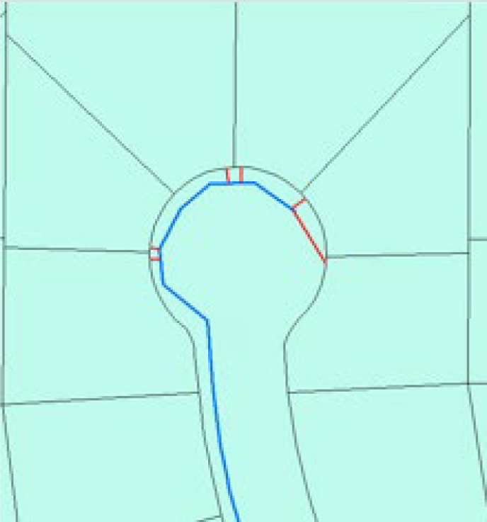
A blow-off or fire hydrant (as applicable) shall be installed at the end of the water main. The water main may be reduced to 4-inch at the end of a residential cul-de-sac, provided:
- Installation of fire hydrants is enough to provide fire protection as specified in this document.
- All meters shall be tapped off the 4” main.
Dead-end water mains in other than cul-de-sac situations will not be allowed, unless approved by the Department. A request for dead-end water mains in other than cul-de-sac situations will be evaluated for approval by the Department on a case-by-case basis. Dead-end water mains allowed for other than cul-de-sacs must include installation of a blow-off valve assembly or fire hydrant assembly (as applicable) for flushing the main, in accordance with Department Standard Details.
2.2.2.4 Clearances and Separations
All water mains shall be installed no closer than five (5) feet from right-of-way lines unless otherwise approved by the Department.
Crepe myrtles, palm trees, and other trees with minimal root systems as approved by the Department may be installed within ten (10) feet of a water main and water services. Horizontal water main and service piping clearance to all other types of trees shall be ten (10) feet or greater.
Provisions of Florida Administrative Code and these Specifications shall govern the design criteria when water mains are installed parallel or perpendicular to sanitary sewers, storm sewers, reclaimed water mains, or gas lines. In the event of differing specifications for a given installation, the most stringent specification shall apply.
Wall-to-wall pipe separation shall, at a minimum, be 12-inch vertical and 36-inch horizontal between water mains and all existing or proposed utilities, except sanitary sewers, metal gas lines, and road underdrains, where the minimum wall-to-wall pipe separations shall be as follows:
| Utility Crossed / Paralleled | Vertical (in.) | Horizontal (in.) |
|---|---|---|
| Storm sewer (gravity) | 121 | 36 |
| Sanitary sewer (gravity) | 121 | 72 |
| Sanitary sewer (pressure) | 121 | 36 |
| Gas line (metal) | 18 | 120 |
| Reclaimed water main | 12 | 36 |
| Underdrains | 18 | 482 |
1 6” minimum separation is acceptable if water crosses above gravity storm or sanitary
2 distance from edge of granular filtration medium to water main
and as further specified below:
- Clearances When Water Main Installations Cross Other Utilities:
- Sanitary sewers, storm sewers, reclaimed water lines, and gas mains shall cross under potable water mains, whenever possible.
- One full length of water main pipe shall be centered at the crossing and its joints shall be leak-free.
- The crossing shall be arranged so that the storm, sanitary sewer, reclaimed water, or gas main joints will be equidistant, and as far as possible, from the water main joints.
- When crossing a metal gas main with 10 feet or less of separation, at a minimum, ductile iron water mains shall be polyethylene encased to a point 20 feet beyond the crossing, in both directions, per Department Standard Detail 2.05 – Polyethylene Encasement Installation.
- Clearances When Water Mains are Installed Parallel to Other Utilities:
- A minimum 6-foot horizontal separation shall be maintained between water mains in parallel installations with sanitary sewers or reclaimed water mains, and a minimum of 3-foot horizontal separation shall be maintained with storm sewers.
- In cases where the minimum horizontal separations cannot be maintained, the following criteria may be applied by the Department:
- The water main may be laid in a separate trench or on an undisturbed earth shelf located on one side of the storm or sanitary sewer at an elevation such that the bottom of the water main is at least 6 inches above the top of the storm or sanitary sewer (in profile view). Minimum horizontal-pipe wall-to-wall clearance of 36 inches shall be maintained.
- The water main should always be above the storm sewer or sanitary sewer (as viewed in profile view) and the joints staggered so as to be located as far as possible from the joints on the gravity or force main.
- If the water main must be below the storm sewer or sanitary sewer, the minimum 12-inch vertical clearance shall be maintained from the bottom of the storm or sanitary sewer to the top of the water main (as viewed in profile view), and a minimum 36-inch wall-to-wall pipe clearance maintained (as viewed in plan-view).
- Proposed water mains installed in parallel with any metal utility line that is cathodically protected, with less than 10-feet horizontal separation (pipe-wall to pipe-wall) shall have the ductile iron water main wrapped in polyethylene encasement for any length wherein the 10-feet separation requirement is not met and for a minimum of 20-feet beyond the limits of non-compliance.
When crossing or installing parallel to storm sewer and sanitary sewer mains, including gravity sewers and force mains, with less than the minimum clearances, the Developer shall protect the water main as shown on the plans or in a manner acceptable to the Department.
Department approval must be obtained for any variance from the above specified clearance and separation requirements.
2.2.2.5 Conflict Manholes
No water main shall pass through, or come into contact with, any part of a sanitary sewer manhole.
Effective August 28, 2003, regulations in the Florida Administrative Code (F.A.C. 62-555.314) were updated to include that water mains shall not be constructed or altered to pass through, or come into contact with, any part of a storm sewer manhole or inlet structure.
Where it is not technically feasible or economically sensible to comply with this requirement (i.e., where there is a conflict in the routing of a water main and a storm sewer and where alternative routing of the water main or storm sewer is not technically feasible or is not economically sensible), the Health Department may allow exceptions to this requirement (i.e., allow construction of conflict manholes); however, persons proposing to construct conflict manholes must first obtain a specific permit from the Health Department, in accordance with F.A.C. 62-555.314 Part V, that provides the technical or economic justification for each exception and provides alternative construction features that afford a similar level of reliability and public health protection, including specific requirements for the conflict manhole construction.
Additionally, the applicant must provide the following in the preliminary design report or drawings, specifications, and design data accompanying their permit application:
- Technical or economic justification for each conflict manhole.
- A statement identifying the party responsible for maintaining each conflict manhole.
- Assurance of compliance with the design and construction requirements in sub-subparagraphs a. through d. of F.A.C. 62-555.314 Part 3.
2.2.2.6 Property Frontage Requirements for Water Main Extensions
2.2.2.6.1 New Buildings
The customer shall front the entire width of their parcel with public water main if they are constructing a new building. Exceptions may be granted by the Department in dead-end right-of-way situations.
2.2.2.6.2 Existing Buildings
The customer shall front ten (10) feet of their parcel with public water main if there is an existing building onsite.
2.2.3 Valves
Valves shall be installed at intervals not to exceed 2,000 feet for transmission mains, 1,000 feet for residential distribution mains, and 500 feet for industrial and commercial distribution mains. There shall be a sufficient number of valves so that single lines in the network may be isolated from the remainder of the system. If construction is to be phased, a valve followed by one full length of pipe, a plug or cap and blow-off valve assembly must be installed at the end of each line that is to be continued. The valve, plug, and all pipe shall be restrained in conformance with this manual.
All tees shall be valved at the tee in 2 directions. All crosses shall be valved at the cross in 3 directions. A valve shall be located on each side of a jack-and-bore crossing and on each side of all water body crossings.
Unless at a tee or cross, valves shall be installed to line up with projected common property lines, if practical. Valve boxes, per current Department Standard Details, shall be installed with all valve installations ≥ 2”. For each valve installation, a Department-acceptable blue (purple if a reclaimed system valve) curb-marker shall also be installed, indicating the general location of the valve.
All valves over 24” must be evaluated and approved via written Water Department consent on a case-by-case basis.
2.2.3.1 Air Release Valves
Air release valves shall be located at high elevation points on the pipeline, where air pockets could disrupt the flow of water. Air release valves provided shall be the automatic-type, whose design is such that the outlet shall be installed above ground, in accordance with Department Standard Details 2.14A “Automatic Air Release Valve”, 2.14B “Automatic Air Release/Air Vacuum Valve”, and 2.15 “Pedestal for Automatic Air Release Valve”, and as required by the FDEP. Air release valves shall be stationed in both plan and profile views in the construction plans.
2.2.3.2 Blow-Off Valve Assemblies
Blow-off valve assemblies shall be installed at the dead-end of all non-circulating mains or at locations directed by the Department. Blow-off assemblies shall be installed in standard # 37 meter boxes set to finished grade. In order to protect it from vehicular traffic, the top of the blow-off-assembly shall be set to an elevation 6-in. below finished grade, inside the meter box. A blow-off valve assembly is not required where a fire hydrant can serve as a flushing location at a water main dead-end.
2.2.4 Fire Hydrants
2.2.4.1 Fire Protection
Fire hydrant spacing dimensions are measured along continuous Fire Department access roads as defined by NFPA 1 Section 18.2.3 2015. If the public fire hydrants meet the NFPA spacing requirements and satisfies the requirements set forth by the local authority enforcing NFPA requirements, any additional hydrants required to be installed by a private property owner shall be privately owned and maintained.
Fire hydrants shall be provided for detached one and two-family residences in accordance with both of the following:
- The maximum distance to a fire hydrant from the closest point on the building shall not exceed 600 ft.
- The maximum distance between fire hydrants shall not exceed 800 ft.
Fire hydrants shall be provided for buildings other than detached one and two-family residences in accordance with:
- The maximum distance between fire hydrants shall be 500 ft or as determined by the Water Department.
The basis of this standard is NFPA 1:18.5.2 “Detached One- and Two-Family Dwellings” and 1:18.5.3 “Buildings Other than Detached One- and Two-Family Dwellings”, 2018 Edition.
Fire hydrants shall be located at least 6-feet from the edge of pavement, including all entryways and driveways. At locations where this distance cannot be provided, bollards shall be required around the hydrant, per Department Standard Details, or as directed by the Department. A bi-directional, blue, reflective pavement marker shall be placed in the center of the traveled lane nearest each fire hydrant.
Per the Florida-specific code requirement of the Florida Fire Prevention Code (NFPA 1:18.5.7), the following minimum clearances to a hydrant shall be provided:
- A 36 in. (914 mm) clear space shall be maintained around the circumference of fire hydrants except as otherwise required or approved.
- A clear space of not less than 60 in. (1524 mm) shall be provided in front of each hydrant connection having a diameter greater than 2-1/2 in. (64 mm).
- Existing, previously approved hydrant installations shall be permitted to have clear spaces less than 60 inches.
Any exception to these distances must have the approval of the Fire Marshall.
2.2.4.2 Water Quality
Blow-off valve assemblies or fire hydrants shall be installed at the dead-end of all non-circulating mains or at locations directed by the Department. Blow-off assemblies shall be installed inside of standard #37 meter boxes set to finished grade, per the applicable Department Standard Details in this manual.
2.2.5 Service Connections
2.2.5.1 When and How Many Are Permissible
Individual water service connections will be required for each parcel for platted single-family residential subdivisions having public right of way. A master water service connection will be provided for single-family residential subdivisions having private right of way, apartments and
condominium complexes. An individual water service connection will be provided for each platted lot therein for platted industrial or commercial subdivisions.
New water services associated with a residential lot split (one lot being converted to a maximum of two lots) along 2 inch water mains are permissible without upsizing the water main. The Tampa Water Department will not issue commitments that extend existing 2” water mains when fire hydrant spacing / standards are not being met.
Commitments for ¾” and 1” residential water services may be issued by Department Customer Service personnel where the property is served by 6, 8, 10, 12 or 14 inch water mains. If the main serving the property is 4 inches or smaller in diameter, an engineering evaluation will be performed to determine water main adequacy to serve the customer. If the main serving the property is larger than those mentioned above, the request for service will be reviewed by Engineering Division personnel to determine the feasibility of a distribution main extension.
Before any distribution mains shall be installed by the Department or authorized by the Department to be installed or before any new commercial or industrial service is connected to an existing water main, such facilities shall include the necessary number of fire hydrants and fire hydrant appurtenances of a size, type, and spacing as specified within this document. The cost of such hydrants and appurtenances may be assessed to the customer.
2.2.5.2 Consecutive Water Supplies
If a customer is considered a consecutive water supplier, the customer is responsible for all associated regulatory compliance. Consecutive systems are defined as below or by FDEP, whichever is more current.
“Consecutive System” is a public water system that receives some or all of its finished water from one or more wholesale systems. Delivery may be through a direct connection or through the distribution system of one or more consecutive systems. (40 C.F.R. §141.2 (July 1, 2011))
“Public Water System” or “PWS” means a system for the provision to the public of water for human consumption through pipes or other constructed conveyances, if such system has at least fifteen service connections or regularly serves an average of at least twenty-five individuals daily at least 60 days out of the year. Such term includes: any collection, treatment, storage, and distribution facilities under control of the operator of such system and used primarily in connection with such system; and any collection or pretreatment storage facilities not under such control which are used primarily in connection with such system. Such term does not include any “special irrigation district.” A public water system is either a “community water system” or a “non-community water system.” See the Code of Federal Regulations (C.F.R.), Title 40, Part 141, Section 2.
2.2.5.3 Sizing
2.2.5.3.1 Meters and Service Lines
The goals of meter and service line sizing are as follows:
- Provide for each customer’s peak flow requirements at Water Department pressure standards
- Provide a standard sizing methodology to ensure fees and rates are consistently administered
- Maximize metering accuracy for revenue optimization and environmental stewardship reasons
Meter sizing is standardized for hydraulic and fee/rate administration reasons. Water Department staff may not be able to accommodate requests for smaller meters due to Water Department connection fees and/or Wastewater Department capacity fees, despite the fact a smaller meter may be hydraulically capable of meeting the customer’s demands. Water Department staff may not be able to accommodate requests for larger meters due to the Water Department’s water conserving rate structure that is sometimes dependent on meter sizing.
Services shall not be installed at a spacing less than every 3 feet along a water main to protect water main integrity.
Meter Sizing
Water meter sizes are determined by the Water Department using AWWA’s Manual of Water Supply Practices M22 “Sizing Water Service Lines and Meters”, the development type, and customer provided:
- Fixture counts (submitted on Water Customer Data Sheet)
- Plumbing plans
- Process water flow demands (submitted on Water Customer Data Sheet)
- Irrigation system plans (submitted on Irrigation Demand Work Sheet)
- Booster pump curves and cut sheets
The following tables present sizing standards based on the predominant development type and total fixture values.
Category 1: Small motels without restaurant or convention facilities; apartments, condominiums, town houses, & small trailer parks less than 300 units; single doctors’ offices; nursing homes; A.C.L.F. & boarding homes; convents; sanatoriums:
| Fixture Value Total | Meter Size | Peak Flow (gpm) |
|---|---|---|
| 0-45 | ¾” Displacement | 0-20 |
| 46-565 | 1” Displacement | 21-50 |
| 566-3000 | 1 ½” Displacement | 51-75 |
| 3001-7150 | 1 ½” Displacement | 76-100 |
| 7151-11000 | 2” Displacement | 101-125 |
| 11001-14000 | 2” Displacement | 126-150 |
| 14001-16000 | 2” Displacement | 151-160 |
| 16001-23750 | 3” Turbine or Compound* | 161-200 |
| 23751-38250 | 3” Turbine or Compound* | 201-300 |
| 38250-60000 | 3” Turbine or Compound* | 301-450 |
| 60001-67500 | 4” Turbine or Compound* | 451-500 |
| *A compound meter is required unless the application reviewer deems a turbine meter appropriate. The basis for this decision will be a case by case determination on the | ||
possibility of flow rates resulting in decreased metering accuracy.
Category 2: Other offices; hotels/motor inns; shopping centers; restaurants; public schools; public buildings; hospitals; industrial parks/attractions; large government installations; laundries; beauty shops; apartments, condominiums, townhouses, or trailer parks of 300 units or more; day care centers; churches:
| Fixture Value Total | Meter Size | Peak Flow (gpm) |
|---|---|---|
| 0-25 | ¾” Displacement | 0-20 |
| 26-105 | 1” Displacement | 21-50 |
| 106-355 | 1 ½” Displacement | 51-75 |
| 356-635 | 1 ½” Displacement | 76-100 |
| 636-1070 | 2” Displacement | 101-125 |
| 1071-2350 | 2” Displacement | 126-150 |
| 2351-3600 | 2” Displacement | 151-160 |
| 3601-10000 | 3” Turbine or Compound* | 161-200 |
| 10001-26000 | 3” Turbine or Compound* | 201-300 |
| 26001-48500 | 3” Turbine or Compound* | 301-450 |
| 48501-55500 | 4” Turbine or Compound* | 451-500 |
*A compound meter is required unless the application reviewer deems a turbine meter appropriate. The basis for this decision will be a case by case determination on the possibility of flow rates resulting in decreased metering accuracy.
Water demands that are not associated with one of the fixture types listed on the Customer Data Sheet shall be stated by the customer in the “process water or special water use” section of the Customer Data Sheet. The customer is responsible for specifying the “process water or special water use” peak flow demand. The application reviewer may require the customer to provide documentation substantiating the stated “process water or special water use” peak flow demand. Peak flow rates for any process water and special water use will be added to the fixture flow to determine peak demand.
The meter size for an individually metered single residential unit (single family residence, one townhome, etc.) will be ¾” unless the customer requests a larger meter. The customer shall substantiate the need for the requested larger meter size.
The peak flow of a booster pump will be utilized when sizing meters. If multiple pumps are proposed in parallel as part of a pumping system (duplex, triplex, etc.), each pump’s peak flow will be added regardless if one pump exists solely for redundancy purposes. If booster pumps with direct suction
taken from meter are proposed, the meter will be sized to provide peak pump flow rates; however, designing oversized pumps will not be considered sufficient reason to install a larger meter than would otherwise be necessary. The application reviewer may require the customer to substantiate booster pump sizing.
If an irrigation system is connected to a domestic water meter, the irrigation demands are typically not considered when sizing the domestic meter. In these circumstances, it is the customer’s responsibility to ensure the irrigation system demand can be supplied by the proposed domestic meter size and at the time of day the irrigation system is anticipated to operate.
Larger meters (>4”) will be sized by the Water Department’s Development Services Section in order to accomplish the above stated goals. Consideration will be given to the pressure drop through the meter (generally 5 psig or less), service piping flow velocity, and corresponding peak flow pressure drop and metering accuracy within the anticipated flow range.
For flows up to 500 gallons per minute, at the application reviewer’s discretion, turbine meters may be utilized for irrigation systems or other similar systems if the metering accuracy curve reflects a favorable metering accuracy at the anticipated minimum flow rate (i.e. the flow associated with the irrigation zone having the least demand or the flow associated with only one of the smallest plumbing fixtures turned on), only if the minimum flow is higher than 1% of its maximum recommended capacity for flow conditions.
Lawn irrigation meters will be sized based on the peak flow rate shown on the customer-submitted Irrigation Demand Worksheet. If a 2-inch or larger irrigation meter would be required, the customer shall submit irrigation plans and calculations with the application to substantiate the irrigation demand.
Combined domestic/fire service meter make, model, and sizing is at the City’s discretion considering flow requirements, pressure, and metering accuracy.
One (1) 1-inch meter will be provided for two duplexes, a tri-plex, or quad-plex, or any combination up to twelve (12) units on one property. Otherwise, these units will be considered as apartments and meter sizing will be determined by AWWA standards.
Meter Sizing Scenarios:
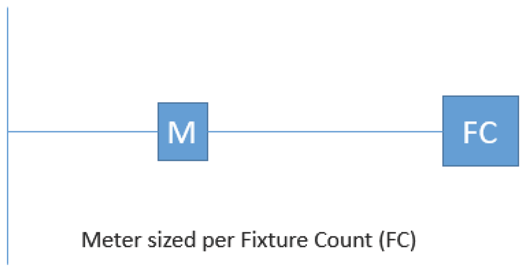
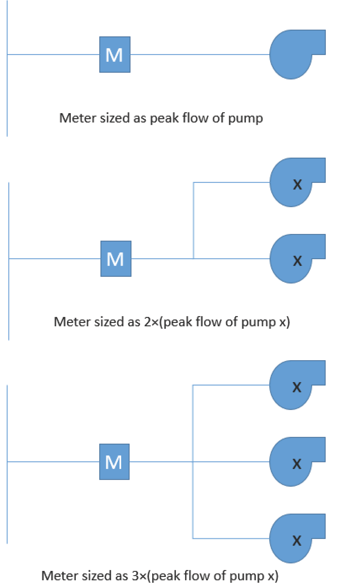 Meter sized as peak flow of pump Meter sized as 2x(peak flow of pump x) Meter sized as 3x{peak flow of pump x)
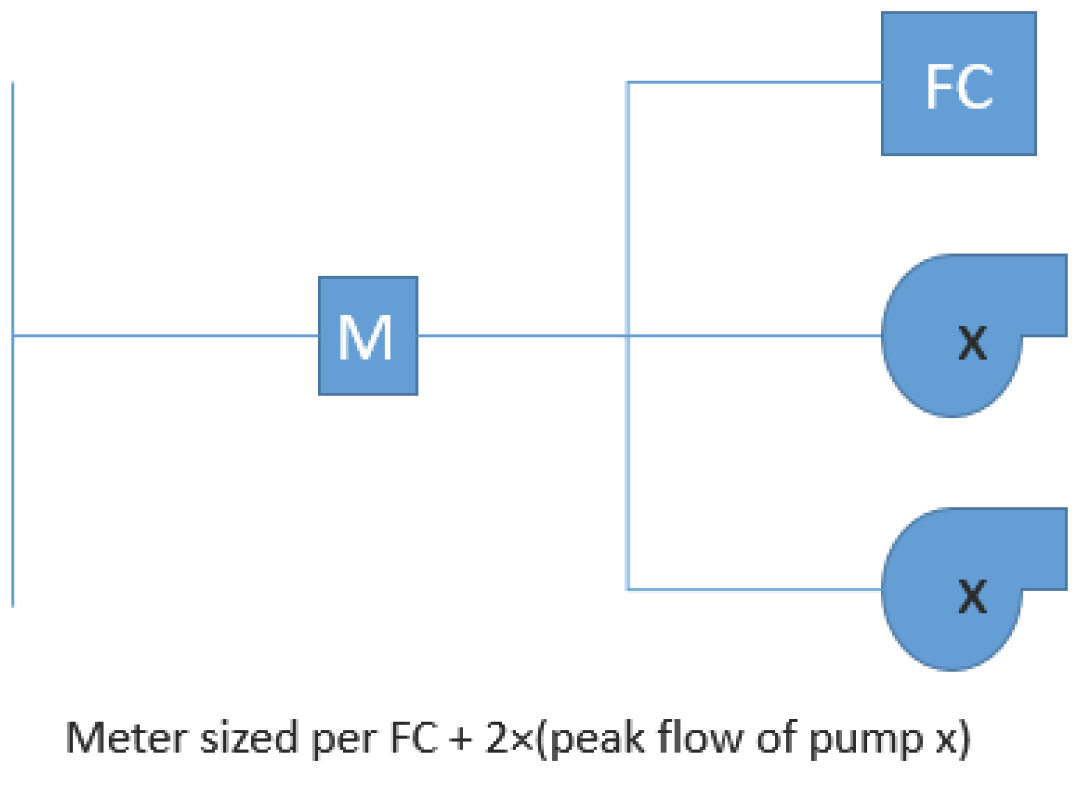
Service Lines
Service lines shall be sized according to Tampa Water Department Standard Details.
2.2.5.3.2 Fire Lines
Each applicant for commitment for fire protection service shall submit a completed Fire Flow Data Sheet.
The Water Department requires that all fire mains must be directly supplied by a distribution main of equal or larger nominal pipe size than the fire main being served.
For single family residential fire sprinkler heads (NFPA 13D Sprinkler Systems), customers may connect to an existing domestic or lawn irrigation system if there is an existing City service large enough for the sprinkler heads. There cannot be more than six sprinkler heads and the peak fire flow
cannot exceed 26 gallons per minutes. A check valve shall be installed by the customer on the fire sprinkler piping near the connection to the existing system. The customer shall submit to the City a completed Fire Flow Data Sheet, calculations, the number of sprinkler heads that would operate simultaneously, the peak gallons per minute demand per head, and the total fire flow demand.
Fire service line sizing shall be as determined by Water Department staff using hydraulic modeling and the criteria listed in Section 2.2.2.2.
Fireline Sizing Scenarios:
2.2.5.3.3 Equivalent Meter Sizes for Combined Domestic/Fire Services
A commitment for water service shall individually indicate the equivalent domestic meter and fire main size in addition to the combined meter size. This is for Wastewater billing purposes.
2.2.5.4 Site and Siting Requirements
Water service connections shall be installed on the address side of the property unless it is determined by the Director or their designee that such connection will provide better service and continuity from a different location.
New small meters (<3”) shall not be installed in sidewalks. New small meters shall be installed in a grassed area between the street curb and sidewalk, or on the customer side of the sidewalk even if said installation will be on private property. The Customer shall be responsible for providing a 5’x5’ grassed area for such installations on private property.
New irrigation meters may not be connected to the potable water system within the reclaimed water service area.
Meter locations will be determined by the Water Department. For single family residences, the meter shall be installed within two (2) feet of the side property line or as directed by the Department. For multiple residential units and lawn irrigation systems, the meter shall be installed where it can be best maintained and serviced.
If a proposed single family residence driveway is in the same footprint as an existing meter box, the Owner is responsible for meter relocation costs and providing a grassed area consistent with Department standards.
No trees may be present within 10 feet of unprotected public water facilities or within five feet of protected public water facilities.
If publicly owned water facilities must be installed within 10’ of a structure, the Owner must provide signed and sealed documentation from a Florida Professional Engineer stating the water facilities and structure do not structurally interfere with each other. Approval of these scenarios is at the discretion of the Water Department.
The Department may require the applicant to provide remote reading registers in accordance with Water Department standards for meters in inaccessible locations.
Per Florida Building Code – Building, 6th Edition (2017), Section [F] 403.3.2: In buildings that are more than 420 feet (128,000 mm) in building height, required fire pumps shall be supplied by connections to no fewer than two water mains located in different streets. Separate supply piping shall be provided between each connection to the water main and the pumps. Each connection and the supply piping between the connection and the pumps shall be sized to supply the flow and pressure required for the pumps to operate. Exception: Two connections to the same main shall be permitted provided the main is valved such that an interruption can be isolated so that the water supply will continue without interruption through no fewer than one of the connections.
New public fire service piping and / or ≥3” domestic services along state or county right-of-way are required to be within an easement dedicated to the City. New public fire service piping and / or ≥3” domestic services along City of Tampa right-of-way shall be within a grassed area acceptable to the Water Department. Grassed areas and easements are generally not required for private fire piping and private fire main backflow preventers.
Minimum Grassed Area and Easement Dimensions for Large Meters (≥3”) and Public Fire Services:
| Underground / Above Ground Types | Minimum Grassed Area or Easement Size12 |
|---|---|
| Underground public detector check valve | 15’ x 20’ |
| Underground 3” or larger meter | 15’ x 20’ |
| Underground public detector check valve and ≥3” meter | 20’ x 20’ |
| Above ground detector check valve and/or ≥3” meter | 20’ x 20’ |
| Water main extensions | Minimum 20’ width along length of water main |
| 1 No shrubbery in the grassed area. 2 Irrigation piping must be removed by applicant prior to construction. | |
Large meters (≥3”) outside of the Special Consideration Area, shown below, shall be installed above ground in accordance with the Department’s design standards. Large meters (≥3”) within the Special Consideration Area may be installed below ground on a case by case basis when approved by the Water Department. Locations within the Special Consideration Area may install below ground vaults in City right-of-way upon Water Department approval.
Special Consideration Area
The Special Consideration Area is defined as the area whose boundary begins at the intersection of the Hillsborough River and the centerline of the northbound I-275 to E Scott St ramp, continues south along the Hillsborough River to Garrison Channel, continues east-northeast along Garrison Channel to Ybor Channel, then north along Ybor Channel to the centerline of Adamo Dr, east along the centerline of Adamo Dr to the centerline of N 26th St, north along the centerline of N 26th St to the centerline of eastbound I-4, west along the centerline of eastbound I-4 to the centerline of N Nebraska Ave, south along the centerline of N Nebraska Ave to the centerline of E 7th Ave, east along the centerline of E 7th Ave to the centerline of Nuccio Pkwy, south along the centerline of Nuccio Pkwy to the centerline of E Cass St, west along the centerline of E Cass St to the centerline of E Tyler St, west along the centerline of E Tyler St to the centerline of N Orange Ave, north along the centerline of N Orange Ave to the centerline of E Scott St, west along the centerline of E Scott St to the centerline of the northbound I-275 to E Scott St ramp, west along the centerline of the northbound I-275 to E Scott St ramp to the intersection of the centerline of the northbound I-275 to E Scott St ramp and the Hillsborough River.
2.2.6 Construction Standards
2.2.6.1 Contractor Requirements
Minimum submittal requirements shall include the following:
- Copy of current State of Florida Underground Utility License
- Insurance coverages (see below)
- Bonded (see below)
- Hold harmless agreement (see below)
- Letter (on company letterhead) listing at least three (3) similar (i.e. same size and scope) underground utility projects recently completed by the Contractor. Construction projects listed may have been outside of Hillsborough County, but preference is for projects in the City of Tampa area. For projects listed, include:
- Name of company or utility responsible for the project
- Contact person with the company or utility including current phone number
- Description of type of work completed and the type of materials installed
Contractor (and Developer) should allow no less than five (5) working days for confirmation of the Contractor’s submitted information. Applications submitted without current telephone numbers could require ten (10) working days or longer to be processed by the Contract Administration Department since the reference information must be verified via ground mail (US Postal Service). The required Pre-Construction Meeting for the Developer Installation will not be scheduled until the Developer’s Contractor is acceptable to the Water Department.
Contractors performing this work must be certified as to expertise by the Water Department, use only Water Department approved materials, and install the services in accordance with Department standards. Contractors' minimum certification requirements include, but are not limited to, furnishing proof of insurance protecting the City in the amount and coverage set forth by current City standards; providing a bond in the amount of five thousand dollars ($5,000.00) or as necessary (as determined by the Water Department Director or their designee) to protect against damage to the City's water system; executing an agreement to hold the City harmless from all claims, suits or actions; and successfully completing examinations administered by the Water Department to measure expertise in meter service installation.
2.2.6.2 Site Preparation
General
The construction site shall be cleared of all obstructions, stumps, roots, and vegetation within the limits required for proper execution of the work in accordance with Section 110, F.D.O.T. “Standard Specifications for Road and Bridge Construction”, latest edition, to a depth of 12-inches.
Since each project may have conditions specific to that project, there may be additional requirements not listed in this section.
Trees
Tree removal shall comply with the laws, ordinances, rules, and/or regulations of the City of Tampa or of any other governmental agencies having jurisdiction. Within the limits of the water pipeline trench, all trees and roots which have been designated for removal shall be labeled on the plans for removal and disposal by the Developer so as to allow for installation of the pipeline without hindrance.
All trees to be removed from City rights-of-way shall require a tree removal permit issued by the Parks Department. All trees to be removed from County rights-of-way shall require a tree removal permit issued by the County.
No trees shall be planted within 10 feet of the water main unless approved by the Water Department.
2.2.6.3 Dewatering
Subsurface water shall be kept 2 feet or more below the invert of the pipe until there is no danger of displacement of pipes or structures. All water collected and pumped shall be disposed of in a manner which will cause no health hazard, flooding, or nuisance to the surrounding area and in a manner so as not to degrade the water quality of surrounding water or violate any environmental ordinances or requirements. Water containing debris, sand, or heavy sediment shall not be discharged into the storm water system. All permits for the discharge of this water shall be obtained by the Developer from the appropriate regulatory agency. All dewatering discharging into surface waters of the state, as defined in Chapter 62-620 F.A.C., shall be tested and discharged in compliance with the “Generic Permit for the Discharge of Produced Ground Water from any Non-Contaminated Site Activity”. Results of pre-dewatering testing shall be maintained on the job site.
Dewatering operations shall be maintained until pipe placement is complete and the trench back-filled sufficiently to prevent movement or flotation of the pipe, including passing density tests if required.
2.2.6.4 Maintaining Service and Shutdowns
Existing water distribution systems must be kept in operation at all times. Where connections must be made to existing mains or when shutdowns are necessary to connect to active water mains, permission must be obtained and arrangements made with the Water Department before removing from service those mains that will be affected. Shutdowns must be held to a minimum in number and duration. No valve or other control device on the existing system shall be operated by the Developer without first obtaining approval from the Water Department. The Developer will be responsible for submitting a pre-valve request form with properly marked plans showing the proposed work with as much notice as possible, but at least four (4) weeks prior to the anticipated shutdown of the existing water system. The Water Department will attempt the requested shutdown and/or identify affected customers to determine shutdown feasibility at its sole discretion. Once the City’s pre-valve operation is complete, a shutdown request form with properly marked plans showing the proposed work must be submitted by the Developer at least two weeks prior to the anticipated shutdown of the existing water system. All pre-valve and shutdown requests must be made to the Water Department through the designated City inspector.
2.2.6.5 Trenching, Backfilling and Compacting
Trenching shall be conducted to the limits and grades shown on the plans or as directed by the Department.
The Developer performing the trench excavation shall comply with the Occupational Safety and Health Administration's (OSHA) trench excavation safety standards, including all subsequent revisions or updates to these standards as adopted by the Department of Labor and Employment Security (DLES).
The Developer shall consider all available geotechnical information in the design of the trench excavation safety system.
The use of trench-digging machinery will be permitted except in places where its operation will cause damage to other utilities, trees, buildings, or existing structures above or below ground, in which case hand methods will be utilized.
The trench width and trenching method may vary with, and depend upon, the depth of the trench and the nature of the excavated material encountered, but in any case shall be of ample width to permit the pipe to be laid and jointed and the backfill properly placed and compacted. The minimum width of unsheeted trench, at the bottom where the pipe is to be laid, shall be two (2) feet greater
than the nominal diameter of the pipe, except by consent of the Department. The maximum clear width of trench and the trench support system shall be in accordance with OSHA requirements.
Where sheeting and bracing are used in a trench, the trench width shall be adjusted accordingly. Trench sheeting shall be cut off at a minimum of one (1) foot above the top of the installed pipe and left in place. Alternatively, the sheeting may be left in place until the pipe has been laid, tested for defects, repaired if necessary, and the soil around the pipe compacted to a depth of two (2) feet over the top of pipe, at which time sheeting may be removed.
The trench shall be AWWA C-600 “Installation of Ductile-Iron Mains and Their Appurtenances” Type 2, as shown on the appropriate Department Standard Details, unless otherwise specified. The trench shall have a flat bottom conforming to the depth to which the pipe is to be laid. The pipe shall be laid upon sound soil, cut true and even, so that the barrel of the pipe will have equal bearing for its full length. Bell depressions of ample dimensions shall be dug at each joint to permit proper pipe jointing.
In the event the Developer excavates below the elevation required without approval from the Department, they shall refill the excavation with approved material and thoroughly consolidate. If, in the opinion of the Department, the trench bottom cannot support the pipe, a further depth and/or width shall be excavated and refilled to pipe foundation grade or other approved means shall be adopted to assure a firm foundation for the pipe.
All excavated material shall be piled in a manner that will not endanger the work and will avoid obstructing sidewalks and driveways. Gutters shall be kept clear or other satisfactory provisions made for street drainage. All material removed from the trench on an improved area shall be removed from the site by the Developer.
Material removed from an unimproved area may be reused if, in the opinion of the Department, it is suitable and if local conditions permit reuse. All materials suitable for reuse must be stored separate from the general excavated material. All backfill material must be approved by the Department prior to placement. If replacement backfill is required, the Developer must supply the material.
Backfilling and compaction shall be conducted in a manner as to prevent subsequent settlement and provide adequate support for the surface treatment, pavement, or structures to be placed thereon.
Backfill material shall be free from cinders, clay, ashes, refuse, organic matter, boulders, rocks or stones exceeding 2-inch diameter, or other material that in the opinion of the Department is unsuitable.
All trenches shall be backfilled and compacted by hand-tamping, from the bottom of the trench to the centerline of the pipe in lifts not to exceed six (6) inches (compacted thickness). Backfill material shall be deposited in the trench full width on each side of the pipe. From the centerline of the pipe to the specified grade, the pipe trench shall be backfilled and compacted by hand or by approved mechanical methods.
Soil consolidation through compaction shall be done in accordance with the requirements of the agency having jurisdiction. Unless requirements of the agency having jurisdiction are more stringent, all compaction shall conform to the following:
2.2.6.5.1 Impervious (Paved) Surface Areas
The space between the pipe and the trench sides shall be packed full by hand-shoveled earth, free from lumps, carefully deposited in layers not exceeding six (6) inches in depth. Such material shall be placed equally on each side of the pipe and, at the same time, tamped in a manner acceptable to the Department, until enough fill has been placed and compacted to the centerline of the pipe. From this point to twelve (12) inches above the pipe, backfill shall be placed and
compacted in uniform loose lifts no greater than six (6) inches to a density that is at least 98% of the maximum modified proctor density as determined by the Modified Proctor Density Test Method (ASTM D-1557). The balance of the soils backfilled from this point to the top of the trench shall be placed and compacted in loose lifts not to exceed twelve (12) inches to a density at least 98% of the maximum modified proctor density.
2.2.6.5.2 Pervious (Non-Paved) Surface Areas
The space between the pipe and the trench sides shall be packed full by hand-shoveled earth, free from lumps, carefully deposited in layers not exceeding six (6) inches in depth. Such material shall be placed equally on each side of the pipe, and at the same time, tamped in a manner acceptable to the Department, until fill has been placed and compacted from the bottom of the trench to the centerline of the pipe. From this point up to grade, backfilled soils shall be placed and compacted in uniform loose lifts no greater than twelve (12) inches, to a density that is at least 95% of the maximum density as determined by the Modified Proctor Density Test (ASTM D-1557).
2.2.6.6 Pipeline Installation
2.2.6.6.1 General
During shipping, delivery and installation of water main pipe, HDPE tubing, and accessories, materials shall be handled in such a manner as to prevent any damage. Particular care shall be taken not to injure pipe coatings. All pipe, fittings, valves, and other material shall be subject to inspection and acceptance by the Department after delivery and no broken, cracked, distorted, imperfectly coated, or otherwise damaged or unsatisfactory material shall be used. When a defect is discovered, the damaged portion shall not be installed. With the Department's approval, cracked DIP shall have the defect cut off at least twelve (12) inches from the break in the sound section of the barrel.
Installations shall be in accordance with manufacturer's recommendations and the appropriate AWWA Standards (C-600 “Installation of Ductile-Iron Mains and Their Appurtenances”) and as described in these technical specifications.
All connections to existing piping systems shall be made as shown or indicated on the plans after consultation and cooperation with the Department. No such connection shall be made until all requirements of these specifications as to tests, cleaning, flushing, and disinfection of new work have been met, and the planned cut-in to the existing line has been approved by the Department. Where connections are made between new work and existing water mains, the connections shall be made in a thorough manner using proper fittings and specials. Some such connections shall be made during off-peak hours if required by the Department.
2.2.6.6.2 Underground Pipelines
Proper implements, tools, and facilities satisfactory to the Department shall be provided and used. Pipe, fittings, valves, and appurtenances shall be carefully lowered into the trench piece by piece. Under no circumstances shall piping materials be dropped or dumped into the trench. Pipe and fittings shall be carefully examined for cracks and other defects while suspended above the trench immediately before installation in final position. If damage occurs to any pipe, fitting, valve, or piping accessory in handling, the damage shall be immediately brought to the Engineer's attention. The Department shall be consulted to prescribe corrective repairs or rejection of the damaged items.
Lumps, blisters, and excess coating shall be removed from the inside of the bell end and outside of the spigot end of each ductile iron pipe. The outside of the spigot and the inside of the bell shall be wire brushed and wiped clean, dry and free from oil and grease before the pipe is laid. Pipe joints shall be made up in accordance with manufacturer's recommendations.
Upon satisfactory excavation of the pipe trench and completion of the pipe bedding, a continuous trough for the pipe barrel and recesses for the pipe bells, or couplings, shall be excavated by hand digging. As the pipe is laid in the prepared trench, true to line-and-grade, the pipe barrel shall receive continuous, uniform support with no pressure exerted on the pipe joints from the trench bottom.
Pipe manufactured from materials that are classified as flexible for purpose of pipe design shall be bedded true to line-and-grade with uniform and continuous support from a firm base and installed in accordance with manufacturer's recommendations. Blocking shall not be used to bring the pipe to grade. Backfill material shall be properly placed and compacted to provide lateral restraint against deflection in the pipe diameter. Care shall be exercised to avoid contact between the pipe and compaction equipment.
The interior of the pipe shall be thoroughly cleaned of all foreign matter before being gently lowered into the trench and shall be kept clean during laying operations by means of plugs or other approved methods. Pipe 12-inches diameter and smaller may be cleaned by flushing in place under the supervision of the Department if in the Department's opinion the pipe contains dirt that can be so removed. In the Department's opinion, if the pipe contains dirt that cannot be removed by flushing, then the pipe shall be cleaned by swabbing and flushing before it is placed in the trench. Pipe greater than 12-inches diameter shall be thoroughly cleaned by appropriate means before being placed in the trench.
During suspension of work for any reason at any time, including the end of each workday, a watertight plug shall be placed in the end of the pipe last laid to prevent mud or other foreign material from entering the pipe. Sufficient backfill material shall also be placed over the pipe to prevent flotation.
Lines shall be laid straight and depth of cover shall be maintained uniformly with respect to finished grade, whether grading is completed or proposed at time of pipe installation. Pipelines shown on the plans to be laid at grade or with a specified slope shall be installed with the top of pipe or invert conforming to the required elevations, slopes, and alignment shown and with the pipe bottom uniformly and continuously supported by a firm bedding and foundation.
The work shall, at all times, progress with caution so as to prevent damage to underground obstructions, both known and unknown. If an obstruction is encountered which is not shown on the plans and realignment is necessary, the Department shall immediately be notified so that alterations to the plans can be made. The Developer shall notify the Department far enough in advance to allow realignment to be accomplished by deflection in the DIP pipe joints.
Pipe shall be laid with bell ends facing upstream, unless directed otherwise by the Department. Wherever it is necessary to deflect ductile iron pipe from a straight line, either in the vertical or horizontal plane, the amount of deflection allowed shall not exceed 80% of that allowed under AWWA C-600 “Installation of Ductile-Iron Mains and Their Appurtenances” for the type of joint being installed. Deflection will be allowed only after the pipe has been properly homed.
- Thrust Restraint
All plugs, caps, tees, bends, hydrant assemblies, and other fittings on water pressure pipelines shall be restrained for the required restraint lengths in accordance with the appropriate Restrained Length Table, as provided in Department Standard Details. Restrained joint lengths shall be called out in the profile views along with the beginning
Precast Thrust Blocks
Thrust restraint shall be accomplished with manufactured mechanical restraint devices. The use of thrust blocks will be considered and approved by the Water Department on a case-by-case basis. Generally, thrust blocks will not be approved unless the Water Department determines mechanical restraint is not feasible. If concrete thrust blocks are required during installation, precast concrete thrust blocks shall be manufactured to the dimensions shown in the Department Standard Details. The concrete for thrust blocks shall consist of a uniform mix of Portland cement, sand, and gravel. The mix shall be proportioned to provide a dense concrete with a minimum compressive strength of 3,000 psi in 28 days. All material used in mixing concrete shall meet Florida Department of Transportation specifications.
Joints
The joints of all pipelines shall be made absolutely tight. The particular joint used shall be acceptable to the Department prior to installation. The gasket material for the joint shall be properly positioned before the pipe is lowered into the trench. The joining of the pipe shall proceed in accordance with the manufacturer's requirements.
Push-on Joints
In making up the push-on type joint, the gasket shall be placed in the socket of the mating bell with the large round end entering first, so that the groove fits over the bend in the seat. The spigot end of the pipe shall be cut and beveled as necessary and thoroughly brushed and cleaned with a wire brush. A thin film of manufacturer-approved lubricant shall be applied to both surfaces (inside surface of bell and outside surface of spigot) to be mated and homed. The spigot end of the pipe shall be placed in alignment with the bell end of the pipe to which it is to be joined. The joint shall be made up by exerting sufficient force on the bell end of the pipe to be homed, so that its spigot end is moved past the gasket until it seats, in accordance with manufacturer's recommendations. Backhoe buckets or excavation equipment shall not be applied directly to the pipe. Any deflections required shall be made after the pipe joint is assembled.
Mechanical Joints
Where shown on the plans, or where in the opinion of the Department, settlement or vibration is likely to occur, all pipe joints of pressure pipelines shall be bolted mechanical type as specified herein.
Mechanical joints shall be made up using high-strength, low-alloy steel bolts and EPDM rubber gaskets having either plain or duck tip as recommended by the manufacturer. All types of mechanical joint pipes shall be laid and jointed in full conformance with the manufacturer's recommendations. Only especially skilled workers shall be permitted to make up mechanical joints.
Mechanical joints shall be centered in the bells. Soapy water or a manufacturer-approved pipe lubricant shall be brushed over the gasket just prior to installation. The gasket and gland shall be placed in position, the bolts inserted, and the nuts tightened finger-tight. Mechanical joints shall be assembled in accordance with AWWA Standards. The joint bolts shall be tightened on opposite sides of the pipes by means of a torque wrench in such a manner that the gland shall be brought up evenly into the joint. The following range of bolt torques shall be applied:
| Bolt Size (inches) | Range of Torque |
|---|---|
| ¾” diameter | 85 to 95 ft-lbs |
| 1” diameter | 95 to 100 ft-lbs |
If effective sealing is not obtained at a maximum torque listed above, the joint shall be disassembled and reassembled after thorough cleaning. If the joint is defective, it shall be cut out and entirely replaced or, if authorized by the Department, the defective joint may be repaired by a suitable clamp.
4) Plugs and Caps
Plugs shall be inserted into the bells of all dead-ends of pipe, tees, or crosses. Plain ends shall be capped. Mechanical restraints for, and restraint lengths of, plugged and capped water mains shall be in conformance with the appropriate Department Standard Details.
5) Polyethylene Encasement
8-mil thick, blue (purple if for reclaimed system) polyethylene encasement shall be installed in conformance with the requirements of AWWA C-105 “Polyethylene Encasement for Ductile-Iron Pipe Systems”, latest revision, Method A and Department Standard Details on all buried ductile iron pipe, fittings, valves, and appurtenances. Polyethylene encasement installation shall be required unless the Department approves otherwise.
6) Pipe Identification
Any run of ductile iron pipe potable water main that is not polyethylene encased shall be wrapped with a continuous length of tape, in accordance with Department Standard Details. Tape for spiral wrapping shall be minimum 2” wide blue (purple if for reclaimed system) vinyl tape, with a minimum of three spiral wraps per pipe section.
High Density Polyethylene (HDPE) service tubing used for potable water services shall be colored blue or shall be identified with a blue stripe containing the word “POTABLE WATER”.
Covers for valve boxes installed over valves in the potable water system shall be painted blue and shall be permanently embossed with “WATER”, per the applicable Department Standard Details.
7) Cleaning and Flushing
All potable water mains shall be cleaned and flushed to remove all sand and other foreign matter. The Developer shall be responsible for developing a cleaning or flushing plan to be submitted to the Chief Construction Engineer for approval prior to the cleaning operation. The Developer’s Contractor shall dispose of all water used for cleaning/flushing without causing a nuisance or property damage, in accordance with state and local requirements. Any permits or fees required for the disposal of flushing water shall be the responsibility of the Developer.
Flushing water used by the Contractor shall be taken from an approved metered source. The Contractor shall obtain the required meter from the Water Department and the Department shall designate the source. Flushing water will be at the Developer’s expense.
Permanent valves and blow-off assemblies shall be used as much as possible to minimize the number of temporary ports required for proper flushing and cleaning.
All materials used shall be specifically manufactured for flushing and cleaning pressure pipes, bends, and valves.
8) Tracer Wire for Long-Side Services
Each long-side service, or any service line over 40 feet, shall have a double-run 10-guage solid copper tracer wire duct-taped onto the top center of the casing pipe. The locater wire should have blue-colored (potable system) or purple-colored (reclaimed system) insulation and be acceptable for direct burial. The wire should be continuous along the service line. All splices require Water Department approval and shall be made with watertight connections if splices are approved.
The locater wire shall have one end sealed off and buried within twelve (12) inches of the connection to the main, with the other end stubbed off in the meter box. Do not wrap or leave locator wire connected to the water service curb stop or fittings. Enough slack shall be provided in the meter box for the wires to extend ten (10) to twelve (12) inches out of the meter box.
The Developer’s Contractor shall perform a tone test on each long-side service using a wire and cable locater. The locater wire shall pass the tone test prior to final acceptance of the service line. Any cuts or breaks in the wire shall be repaired by the Contractor at their expense.
9) Completion
After the pipe has been laid, inspected by the Department and found to be satisfactory, backfill shall be placed per Department Standard Details, or per backfilling specifications of the applicable agency controlling the rights-of-way, and a hydrostatic test conducted, per Section 2.2.7 “Requirements for Acceptance”. Developer-installed water mains will not be accepted by the City until tests have been completed to the satisfaction of the Department.
2.2.6.6.3 Above Ground and Exposed Piping
Above ground and exposed pipe, fittings, valves and accessories shall be installed as shown or indicated on the plans. Piping shall be cut accurately to measurements established at the job site and shall be worked into place without springing or forcing, properly clearing all equipment access areas and openings. Pipe connections shall be made in accordance with the details shown and manufacturer's recommendations. Open ends of pipes shall be properly capped or plugged during installation to keep dirt and other foreign material out of the system. Pipe supports and hangers shall be provided where indicated or as required to ensure adequate support of the piping.
2.2.6.7 Casing Installation
Casing installation for water distribution or transmission mains shall be performed by jacking-and-boring under highways and railroads where shown on the plans. The casing pipe size, thickness, length, location, and detail shall be as indicated and specified in Department Standard Details, and as described below. The work shall be performed by a qualified contractor, experienced and
regularly engaged in jack-and-bore installations. All necessary materials, equipment, labor, and traffic protection devices shall be on the job site before starting the work.
The Developer shall strictly adhere to Florida Department of Transportation Utility Accommodation Guide, Hillsborough County Utility Accommodation Guide, CSX Transportation Inc./Seaboard System Railroad Standard Specifications for Pipelines, AASHTO Standards, and requirements of any other agency, whether public or private, having jurisdiction over the highway/railroad concerned. Requirements may be established verbally from an on-site representative, in the form of a written notice or permit, or transmitted through the Department. No construction or mobilization shall commence until the necessary permits have been obtained, a copy of the permit is at the job site, and proper notice and approval for construction have been obtained from the Department.
Casing pipe shall be welded-steel pipe having minimum sizes and thickness as shown in the applicable Department Standard Details. The steel shall meet the requirements of ASTM A139, Grade B. The Developer may use a welded-steel casing pipe of a larger diameter than specified if approved by the Department.
Only new pipe shall be used and all surfaces shall be smooth and uniform without bulges, dents, or warping. Finished lengths of pipe shall have beveled cut ends to facilitate proper welding of transverse joints. The casing may need bituminous coating if required by the agency having jurisdiction over the jacking-and-boring site. Prior to ordering equipment and materials for the jacking-and-boring operation, the Developer shall get approval of their jacking equipment from the Department.
Hydraulic jacks shall be used in the jacking operation and extreme care shall be taken to maintain exact line and grade. Excavation at the heading shall be advanced not more than one foot ahead of the casing pipe and may be done manually or with an auger. Reaction blocks shall be utilized and adequately designed to carry the thrust of the jacks to the soil without excessive soil deflection and in such a manner as to avoid any disturbance of adjacent structures or utilities. Adequate protection railings shall be provided at the top of the pit at all times.
The jacking pit shall be of adequate length to provide room for the jacking frame, the jacking head, the reaction blocks, the jacking auger rig, and the jacking pipe. The pit shall be sufficiently wide to allow ample working space on each side of the jacking frame. The depth of the pit shall be such that the invert of the pipe, when placed on the guide frame, will be at the elevation desired for the completed line. The pit shall be tightly sheeted where necessary and kept dry at all times. The jacking frame shall be designed so that it applies a uniform pressure over the entire pipe wall area of the pipe to be jacked.
Extreme care shall be taken to ensure that the casing is installed to accurate line-and-grade; maximum acceptable error in any direction from the design grade and alignment shall be 1/8-inch per foot or as directed by the Department.
Upon completion, the Developer shall obtain and furnish to the Department a written release from the governing agency indicating satisfactory completion of the crossing.
2.2.6.8 Fittings
Fittings shall be handled with care to avoid damage. All fittings shall be loaded and unloaded by lifting, and under no circumstances shall fittings be dropped, skidded, or rolled. Under no circumstances shall fittings be placed against pipe or other fittings in such a manner that damage could result. Slings, hooks, or tongs used for lifting shall be padded in such a manner as to prevent damage of exterior surface or interior lining of fittings. If any part of the coating or lining of a fitting is damaged by the Developer, the Developer shall repair or replace the fitting to the satisfaction of the Department before installing. Fittings
shall be stored at all times in a safe manner to prevent damage and to be kept free of dirt, mud, or other foreign matter. All fitting gaskets shall be stored and placed in a cool location, out of direct sunlight, and out of contact with petroleum products. All gaskets shall be used on a first-in, first-out basis.
2.2.6.8.1 Anchorage of Tees, Bends and Plugs
Adequate precautions shall be taken to prevent the separation of joints at bends, tees, and plugged ends.
Details of design, construction, applications, installations, and number of joints necessary for the restraint of a given thrust shall be as specified in these specifications and/or as indicated on the plans. Under no circumstances will gray iron pipe be used at restrained joints; ductile iron pipe shall be installed for City water mains unless otherwise authorized by the Department. Thrust restraint provided for all new-pipe City water installations shall be through mechanical restraint devices, devices which provide restraint through mechanical actions equivalent to or better than either the Megalug restraint device, for exterior restraint of mechanical joints, or the gripper-type gasket restraint, for providing thrust restraint through the pipe bell-and-spigots.
Where reaction or thrust blocking is required (and only if thrust blocks are authorized by the Water Department), it shall be of concrete meeting the following design criteria:
| Criteria | Requirement |
|---|---|
| Compressive Strength | 3,000 psi |
| Air Entrainment | 5.0% |
| Water/Cement Ratio | 0.45 |
| Max. Aggregate Size | ½ in. |
| Slump Range | 3-4 in. |
Blocking shall be placed between undisturbed earth and the fitting to be anchored where firm support can be obtained. The area of bearing on the pipe and on the ground in each instance shall be that shown on the plans, the Standard Detail, or as directed by the Department. The fittings shall be polyethylene encased in a manner acceptable to the Department prior to blocking. The blocking shall, unless otherwise shown or directed, be placed so that the pipe and fitting joints will be accessible for repair. If the soil does not provide firm support, then suitable tie rods, bridles, clamps, and accessories as specified by the pipe manufacturer to brace the fitting properly shall be provided.
Precast thrust blocks may be used in lieu of poured-in-place blocks on 8-inch and smaller water mains only. Precast blocks must be manufactured in accordance with these Technical Specifications. Size and bearing area of blocks will be as determined by the Department. The Department has the authority to reject any damaged block or any block considered of questionable quality. Placement will be in accordance with standard procedures for restraining thrust. Soils behind such blocks will be either undisturbed or compacted to a density that is a minimum 98% of the modified proctor density.
Tie-rods and pipe-clamps, when allowed by the Department, must be of adequate strength to prevent movement or other suitable means may be used as allowed by the Department. Steel rods, clamps, and washers shall be rustproof treated with bituminous material and polyethylene encased.
2.2.6.9 Valves
Valves shall be handled with care to avoid damage. All valves shall be loaded and unloaded by lifting and under no circumstances shall valves be dropped, skidded, or rolled. Valves shall not be
placed, under any circumstances, against pipe or other fittings in such a manner that damage could result. Slings, hooks, or tongs used for lifting shall be padded in such a manner as to prevent damage. If any part of a valve’s exterior coating or interior lining is damaged by the Developer during handling, the repair and replacement shall be made by the Developer at their expense in a manner satisfactory to the Department before installing. Valves shall be stored at all times in a safe manner to prevent damage and kept free of dirt, mud, or other foreign matter. All valve gaskets shall be stored and placed in a cool location, out of direct sunlight, and out of contact with petroleum products. All gaskets shall be used on a first-in, first-out basis.
Valves shall be set and joined to new pipe in a manner previously specified for the cleaning, placement, and joining of pipe.
Cast iron valve boxes shall be firmly supported, centered, and plumb over the operating nut of the valve and the cover shall be flush with the surface of the finished pavement or at such other levels as may be directed. Valve boxes installed outside the horizontal limits of paved roadways, paved driveways or sidewalks shall have 6-inch thick wire mesh reinforced concrete pads poured around the top section of the valve box. In accordance with Department Standard Details, the pad shall be 24-inches square or round and shall be centered on the valve box. All Department potable water valve covers shall be painted safety blue as prescribed by the American Public Works Association (APWA) uniform color code for utility systems.
The valve and valve box shall be installed such that Department personnel can insert a valve key through the valve box and completely open and close the valve. This test will be accomplished before final acceptance of the valve into the water system.
2.2.6.10 Taps
All taps of, or connections to, existing City-owned water mains shall be approved by the Water Department.
All material supplied for the tapping operation shall be disinfected in accordance with Department standards.
After the Contractor installs the tapping sleeve and valve, and before the tap is made, the sleeve will be tested to ensure a watertight joint. A test plug will be provided in the sleeve, and after the sleeve has been installed, it will be filled with water and the pressure increased to between 150 and 190 psi. All leaking joints will be repaired to the satisfaction of the Department at the Developer's expense. The pressure test must be witnessed by the City. Taps of existing water mains will be performed by City of Tampa Water Department personnel only or a Department approved contractor. Due to workload constraints, taps by Water Department personnel will not be scheduled on Mondays or Fridays.
All tapping sleeves shall be wrapped and sealed in an approved manner with approved polyethylene encasement material.
All taps for meter services on PVC mains shall require use of a service saddle, manufactured specifically for PVC pipe. Developers shall not use double-strap saddles designed for ductile iron or not formed to exact size for proper fit. The cutting tool shall be a shell-type (hole) cutter for PVC pipe with internal teeth or double slots and be designed to accommodate AWWA C-900 pipe; use of twist drill bits and auger bits is prohibited. Saddles used must provide support around the full circumference of the pipe and provide bearing area of sufficient width along the axis of the pipe (2-inches minimum) to ensure that the pipe will not be distorted when the saddle is tightened.
2.2.6.11 Hydrants
2.2.6.11.1 Installation
Fire hydrants shall be handled so as to avoid any damage at all times. Hydrants shall be located consistent with NFPA requirements, in a manner to provide complete accessibility and that the possibility of damage from vehicles or injury to pedestrians will be minimized. Fire hydrants in FDOT rights-of-way shall conform to FDOT clear zone requirements.
Unless otherwise directed, the setting of any hydrant shall be as described in these Technical Specifications and as illustrated in Department Standard Details. All fire hydrants shall be thoroughly cleaned of dirt or foreign material before installation. All hydrants shall stand plumb and shall have their pumper nozzle perpendicular to the curb. The bottom flange elevation shall be finished grade plus 3- to 5-inches. Standard depth of bury shall be 3 to 5 feet, as measured from top of pipe of the hydrant lead to finished grade. Each hydrant shall be connected to the water main with a 6-inch DIP branch (hydrant lead) controlled by an independent 6-inch resilient seat gate valve hydrant shut-off.
All fire hydrant leads shall be made of ductile iron pipe. All fire hydrant tees shall be made of ductile iron.
All hydrants shall be anchored by restraint fittings as specified in this manual and as specified in the Department Standard Details.
All hydrant sets shall include the installation of a concrete thrust collar around the barrel of the hydrant, 12 inches below the ground line.
Upon completion of installation and passing all required tests, the fire hydrant barrel above the ground line shall be painted with a high-grade enamel paint, Federal Safety Yellow (OSHA approved), and the bonnet shall be painted the appropriate color based on flow test results.
A bi-directional, blue, reflective pavement marker (RPM) shall be installed adjacent to each hydrant, in the center of the travel lane nearest the hydrant. The RPM and the adhesive used to anchor it to the road surface shall conform to all appropriate provisions of the Florida Department of Transportation “Standard Specifications for Road and Bridge Construction”.
2.2.6.11.2 Protection Posts
Fire hydrant protection posts are required when the fire hydrant is less than six (6) feet from the edge of pavement, or as directed by the Department Reviewing Engineer. Protection posts shall be placed three (3) feet from the center line of the hydrant facing the edge of pavement and 1-½ feet from the centerline of the hydrant facing oncoming traffic per Department Standard Detail. The number of posts required will depend upon the fire hydrant's exposure to traffic.
Fire hydrant protection posts shall be 6-inch diameter ductile iron pipes with smooth rounded tops. Posts shall be filled with concrete and set a minimum of three (3) feet above and two (2) feet below grade. Posts shall be painted with high-grade enamel Federal Safety Yellow (OSHA approved).
Protection posts must be installed so that the hydrant may be fully operated with a standard hydrant wrench without the need to remove the wrench.
2.2.6.12 Backflow Preventers
All backflow prevention devices shall meet the performance standards established by the American Water Works Association, the Foundation for Cross-Connection Control and Hydraulic Research (a
2.2.7 Requirements for Acceptance
2.2.7.1 General
All Developer-installed water facilities must be constructed in accordance with all applicable Department Standards and Specifications, Standard Details, and City of Tampa Code requirements. A representative of the Department will inspect the construction to assure compliance.
2.2.7.2 Testing
The Department will require the Developer's Engineer of Record to perform the required tests to assure that all pipe installed including service lines meets the Department's standards.
The required tests are as follows:
2.2.7.2.1 Hydrostatic Testing
Pressure Testing
All newly laid water pipe, including fittings, valves and service lines, shall be pressure tested in accordance with AWWA C-600 “Installation of Ductile-Iron Mains and Their Appurtenances” for DIP.
The Developer shall furnish, install, and operate all necessary equipment and instrumentation (pressure gauges, volume gauges, hoses, pumps, test pipe, test fittings, etc.) required for flushing and testing of the piping systems; all such equipment and devices and their installation shall be approved by the Department. Pressure gauges shall be marked in graduated increments that do not exceed 2 psi. Gauges used to measure the volume of water necessary to raise post-test line pressure back to the highest pressure achieved during the test duration will be marked in graduated increments which do not exceed 5 ounces.
If requested by the Department, the Developer shall furnish to the Department certified test data for any gauges or recorders used for testing purposes. For testing purposes, the Developer shall have access to water supplied by the Department. Testing shall be conducted in the presence, and to the satisfaction, of the Department as a condition precedent to the approval and acceptance of the system. No less than 3 days’ notice shall be given prior to start of such tests; such testing shall not be scheduled until preliminary testing by the Developer has indicated that the test section is ready for testing. The schedule and procedures for testing shall be determined by the Developer and reviewed with the Department prior to testing.
The duration of each pressure test shall be at least 2 hours with a minimum test pressure in excess of 150 psi. At no time shall the test or line pressure exceed 190 psi. Test pressure shall not vary by more than ±5 psi for the duration of the test. If required by the Department, pump test equipment will be equipped with pressure relief valves pre-set to 190 psi. Each valved section of pipe shall be slowly filled with water and a pump shall be connected to the low point of the section being tested.
Before conducting the test, the Developer shall backfill all pipe unless the Department directs certain joints or connections to be left uncovered.
Before application of the test pressure, all air shall be expelled from the pipe. To accomplish this, taps will be made, if necessary, at points of highest elevation and afterward tightly stopped with tapered brass plugs, all at the Developer's expense.
At the end of the 2-hour test period, the Developer shall be required to pump the lines back up to the highest pressure obtained during the duration of the test period.
Pressure tests shall be made between valves to demonstrate the ability of the valve to sustain pressure. All piping systems shall be tested in accordance with these test methods, in addition to any other tests required by local plumbing codes or building authorities. At the option of the Department, flow meters and/or pressure gauges used on hydrostatic testing equipment with approved strip or round chart recorders shall be supplied by the Developer. Tests shall be made in sections not to exceed ½ mile.
Throughout the duration of the test, the Developer is required to maintain a minimum pressure in excess of 150 psi. The Developer is advised that, should the test pressure fall to or below 150 psi any time during the 2-hour test, the test will be considered invalid and a retest will be required. Therefore, it is advised that the Developer should pump water into the line as the test pressure approaches 150 psi.
The Department may allow pressure testing of multiple sections during one continuous 2 hour test period as long as the Developer can justify that each valved section shall be tested to the satisfaction of the Department.
The Developer is warned that pressure testing against existing valves is done at their own risk. Failure of these valves to hold test pressure shall not relieve the Developer of the pressure testing requirement.
All exposed pipe, fittings, valves, and joints shall be carefully examined for leaks. Any cracked or defective pipe, fittings, valves, or other appurtenances discovered as a consequence of the pressure test shall be removed and replaced with acceptable material, at the Developer’s expense. All leaking or defective joints shall be repaired, corrected, or replaced, at the Developer’s expense. After all necessary replacements and corrections have been made the test shall be repeated to the satisfaction of the Department.
If the pipeline fails the pressure test twice, then the Developer shall be required to retest the pipeline and provide to the Department certification by a Professional Engineer registered in the State of Florida that the pipeline has passed the test in accordance with these standards before the Department will witness another test.
Leakage Testing
Concurrently with pressure testing, pipelines shall be subjected to leakage tests.
Leakage measurements shall not be started until a constant test pressure has been established in excess of 150 psi.
The duration of each leakage test shall be at least 2 hours and the test pressure shall be as specified for the pressure tests. Leakage is defined as the quantity of water that must be supplied into the pipeline or section thereof to maintain the established test pressure after the air in the pipeline has been expelled and the pipe filled with water plus that volume of water required at the conclusion of the test to bring the line pressure back up to the highest pressure obtained during the duration of the test period.
The maximum allowable leakage shall not exceed the number of gallons per hour (gph) as determined by the following formula:
LL = SS x sqrt(P) / 148,000
where: L – allowable leakage, gph
- S – length of pipeline tested, feet
- D – pipe nominal diameter, in inches
- P – average pressure during the test, psi
The allowable leakage equation given above is based on 18-foot lengths of pipe and shall be adjusted accordingly for other pipe lengths supplied.
AWWA C-600 “Installation of Ductile-Iron Mains and Their Appurtenances” includes a table which provides the allowable amount of leakage in gallons per hour for various sizes of pipe under different test pressures. The Developer is referred to that table as an alternative to calculating the values using the above formula.
When leakage exceeds the allowable limit, the defective pipe or joints shall be located and repaired. All visible leaks are to be repaired regardless of the amount of leakage. If the defective portions cannot be located, the Developer shall remove and reconstruct as much of the work as is necessary until the leakage is within the allowable limits. Such corrective work or damages to other parts of the work as a result of such work shall be at the Developer's expense.
Leakage detection at mechanical joints shall be stopped by tightening the gland (not to exceed required torque) and leaking slip joints shall be cut out and entirely replaced or if permission is given by the Engineer, with technical assistance from the City of Tampa Water Department, it may be repaired by a suitable clamp. Any cracked or defective pipe, fittings, valves, or hydrants discovered as a result of this test shall be removed and replaced by the Developer with sound material and then the test shall be repeated.
If the pipeline fails the leakage test twice, then the Developer shall be required to retest the pipeline and provide to the Department certification by a Professional Engineer registered in the State of Florida that the pipeline has passed the test in accordance with these standards before the Department will witness another test.
2.2.7.2.2 Disinfection
The Developer shall disinfect the water mains in accordance with the applicable section of the latest AWWA C-651 “Disinfecting Water Mains”, as summarized below. The Developer, if directed, shall use the method specified by the Engineer.
Methods of Chlorination:
- Slug Method
- The slug method consists of:
- a) Completely filling the main in order to remove air pockets.
- b) Flushing the main with a velocity of not less than 2.5 feet per second (fps) in order to remove particles.
- c) At a point not more than 10 feet downstream of the water source flushing the new main, chlorine is to be continuously injected for a sufficient period to develop a solid column or "slug" of chlorinated water.
- d) The slug of chlorinated water is to move through the main, exposing all interior surfaces to a chlorine concentration of approximately 100 mg/L for at least a 3-hour period.
- Continuous Feed Method
The continuous feed chlorination method consists of:
- Completely filling the main to remove air pockets.
- Flushing the main with a velocity not less than 2.5 fps.
- At a point not more than 10 feet downstream of the water source flushing the new main, injecting chlorine in the new main at a constant rate sufficient to establish a 25 mg/L chlorine concentration throughout the main.
- Minimum amount of chlorine required for each 100 foot section of pipe of various diameters:
| Pipe Diameter | 100% Chlorine (lb) | 1% Chlorine Solution (gal) |
|---|---|---|
| 4" | 0.013 | 0.16 |
| 6" | 0.030 | 0.36 |
| 8" | 0.054 | 0.65 |
| 12" | 0.120 | 1.44 |
| 16" | 0.217 | 2.60 |
- The chlorinated water shall be retained in the main for at least 24 hours and have a residual of not less than 10 mg/L free chlorine prior to flushing.
2.2.7.2.3 Sampling
Upon completion of the hydrostatic test and disinfection, and at least one week in advance of the sampling, the Developer shall contact the Department's Contract Administration Department to request coordination and inspection for bacteriological testing. The Developer shall employ a private, City-approved testing lab for the required Bacteriological sampling and testing.
The Developer shall install sample taps, per Department Standard Details, on the new main and at the end of each new branch of the piping system. The Developer shall flush the chlorinated disinfection water from the piping system until a free chlorine residual of 1.0 to 1.5 mg/L is maintained.
Due to FDEP requirements, the Developer’s Contractor may be required to remobilize to the site thirty to forty-five days after the samples have been cleared to perform necessary meter transfers and/or cut-and-plugs.
All drilling and tapping equipment shall be disinfected as directed by the Department.
After completing the testing and sterilizing, and regardless of ground conditions, all sample taps and corporation stops shall be removed from the water main and replaced with tapered brass plugs.
2.2.7.3 Restoration
2.2.7.3.1 Waste Material Disposal
The Developer shall remove and dispose of all debris and excess spoil resulting from clearing, demolition, and excavation operations. Natural waterways or bodies of water shall not be used for disposal of debris.
All debris shall be disposed of at a site approved and permitted by the State for such disposal. Clean spoil may be disposed of on private property only with written authorization of the property owner.
Burning of brush or debris is not permitted.
2.2.7.3.2 Repair and Resurfacing
Where street paving, driveways, sidewalks, or curb and gutter are disturbed, restoration shall be made to a condition at least equal to the original. All materials used for restoration shall conform to standard requirements of that particular agency responsible for roadway maintenance where construction takes place. All restoration work shall also meet the requirements of both the permitting agency as well as the Department. The Developer shall determine any requirements and procedures, other than those set forth herein, which may affect the type, quality, and method of carrying out the restoration of the areas to be restored to the satisfaction of the Department.
Base material shall be of the type removed or of equal or greater structural strength as determined by the Engineer. Existing base material from the excavation shall not be reused as base material, but may be used as a stabilizer, or for trench backfill after removal of existing asphalt, unless it is determined by the Department to be unsuitable.
Edges of pavement shall be mechanically sawed to provide a neat, straight edge to the width shown on the construction plans, or greater if necessary, prior to replacement. Base material shall be placed to the depths required by the permitting agency and thoroughly compacted to the density required by the Department or to the standard of the governing permitting agency.
The Developer shall pay careful attention to the proper reconstruction of the pavement adjacent to the gutters and at street intersections to obtain satisfactory drainage to inlets from the intersecting streets. Pavement replacement shall be with the same type of materials as removed and installation methods and procedures shall comply with the appropriate procedures established by the FDOT Standard Specifications, or the appropriate permitting agency.
In the absence of governing agency requirements, where asphaltic concrete overlays are performed, the overlays shall be 1-inch thick over the pipe trench area, or as directed by the Department, and provide smooth transition between existing pavements and overlay pavement.
Permanent pavement replacement shall not commence until acceptable to the Department. Until such replacement is completed, the Developer shall maintain all trenches and disturbed areas, providing additional base materials as is necessary to maintain smooth transition of the areas by vehicular traffic and providing dust control as necessary.
2.2.7.3.2.1 City of Tampa Owned Right-of-Way Requirements
City of Tampa roadway restoration requirements, as of 2012, are as follows. Any subsequently issued City of Tampa roadway restoration requirements are herein incorporated via reference.
Pavement options:
| Pavement (Classification) | Base | Concrete | Asphalt Surface | Full Depth Asphalt |
|---|---|---|---|---|
| A | 6” | 4” | 1” | 5” |
| I | 8” | 6” | 2” | 7” |
| II | 12” | 8” | 3” | 10” |
Pavement Restoration Specifications
Classification:
- Class A: Alleyways and Residential and Low Volume Commercial Driveways
- Class I: Two-Lane Residential Streets and High Volume Commercial Driveways
- Class II: Multi-Lane or High Volume Two-Lane Streets (most depicted by centerline markings)
Notes:
- If existing roadway is stabilized, increase base material thickness by 50%.
- If original pavement exceeds maximum 3”, match the existing asphalt thickness.
- Minimum 4” of shell marl, crush concrete, or asphalt millings placed in unimproved (dirt) trafficked right-of-way.
- Concrete shock pad required for any utility repaired/installed less than 30” (needs City of Tampa Engineer approval).
- Brick pavement shall be restored as specified under Brick Replacement.
Backfill and Subgrade
Replace and compact clean sub-grade material classified as A-1, A-2, or A-3. Backfill shall be free of objectionable material (bricks, broken pavement, concrete, clay, muck, etc.). If flowable fill is used, both mix and installation shall conform to FDOT Standard Specifications for Road and Bridge Construction (January 2000), Section 121-1 through 121-6.
Density Requirements
Material shall be compacted in lifts not to exceed 12”. Densities are required at alternative 1’ lifts of vertical fill above excavation bottom of trench and for each prepared trench segment, not to exceed 200’. Density test is not to be taken through succeeding layers. The final subgrade density test shall be taken at elevation beneath Base Material or Full Depth.
Density Specifications
Shall meet 98% compaction of AASHTO T-180.
Base Material
Approved by a City of Tampa Engineer and/or meeting the FDOT Standard Specifications for Road and Bridge Construction (January 2000). Submittal may be requested by City of Tampa.
Acceptable Materials
Limerock, Shell Marl, Crushed Concrete, Concrete (3000 minimum psi), and Asphalt Plant Mix.
Density Requirements
Place and compact in two lifts. Asphalt Plant Mix shall be compacted in accordance to Asphalt Surface requirements. Densities are required for each trench segment at final grade, not to exceed 200’.
Density Specifications
Shall meet 98% compaction of AASHTO T-180.
Concrete
3000 psi minimum 28-day strength. Placed on compacted, moistened subgrade. Consolidate and cure. Do not load for 72 hours.
Concrete Specifications
Density test of subgrade may be required at the Inspector’s discretion.
Asphalt Surface and Full Depth Asphalt
Sawcut all sides a minimum of 6” from replaced base. Paint with RC 70, or equal, tack. Place and compact in lifts S-1 or S-3 type Asphalt Plant Mix. The finished pavement is subject to inspection and approval by City of Tampa DPW Engineer.
Density Requirements
Type S-1 lift to be 1-1/4” minimum and 3” maximum; if lift exceeds 2”, compact with a drum roller type compactor. Type S-3 lift to be ¾” minimum and 1-1/2” maximum.
Density Specifications
Quality assurance testing of the asphalt may be required at the Inspector’s discretion. Generally: 96% compaction of Asphalt Plant Mix design bulk specific gravity.
Brick Replacement
Brick shall be re-laid according to Procedures section below. Place and grade 1-1/2” of sand over base or concrete. Place brick uniformly, staggered with respect to the adjacent course. Any work area disturbing a street listed as “Historic Street” shall be required to replace original brick. The Contractor is responsible for safe storage of materials until such time the brick is re-laid.
Base Options
- Limerock and Shell Marl: Shall meet above Base Material specifications. Requires brick joints to be sealed with Asphaltic Steep #7330 or Surebound 1300 Sealer.
- Crushed Concrete: Shall meet above Base Material specifications. Requires brick joints to be sealed with 1:4 sand/cement mixture, slurry or moistened to ensure that cement sets.
- Concrete: Shall meet above Concrete specifications. 4” of concrete is used as base material. Requires brick joints to be sealed with 1:4 sand/cement mixture, slurry or moistened to ensure that cement sets
Density Requirements
Subgrade material shall meet above Backfill and Subgrade standards. Base material shall meet above Base Material specifications.
Density Specifications
Shall meet 98% compaction of AASHTO T-180.
Pavement Restoration Procedures
General
The Permit Holder is to contact the Transportation and Stormwater Department 48 hours prior to starting permitted work. The material testing results should be forwarded to the department/inspection group performing the inspection.
Testing/Inspection shall be scheduled with the City of Tampa Materials Testing and Inspections on any part of the replacement work. Tests will be performed by the City’s Testing/Inspections Lab or an approved private engineering testing laboratory. The permittee shall bear all testing costs.
The Foreman on each project shall maintain onsite copies of the approved Department of Public Works “Application and Permit for Construction and Maintenance Operations Within Public Rights of Way”, including plans, drawings, and the Pavement Restoration Requirements – 2003.
Copies of all applicable material delivery tickets and copies of all test results not taken by DPW Materials Testing and Inspections shall be forwarded to DPW Technical Services at 3806 26 Ave E, Tampa, FL 33605. Fax number (813) 622-1956.
Excavation
Utility installations shall be placed a minimum of 30” below grade. If the 30” minimum depth requirement cannot be maintained, because of utility conflicts or unusual conditions, special authorization may be granted for installation at a lesser depth. Installations shall maintain the 30” depth, unless special authorization is granted in writing by the DPW Engineer.
All trench widths under pavement, including driveways, are to be a minimum of 18” to allow mechanical compaction of backfill and base. Density tests are required and restoration shall meet the above specifications.
Where pavement and/or base are undermined, disturbed, or otherwise damaged, such areas shall be cut away and the pavement replacement work extended to correct such conditions.
Tunneling under driveways, sidewalks, curbing, retaining walls, and pavement shall not be allowed unless approved prior to work is given by City of Tampa Engineer.
When obstructions are encountered in driving or jacking, pipe shall be cut off, left in place, and filled with a flowable fill type grout to prevent the formation of voids.
Edges of jacking pits, directional pits, exit pits, trenches, etc. shall be a minimum distance, equal to the depth of the pit excavation, from any pavement, curbs, sidewalks, or other structures. If this distance cannot be maintained, backfill shall be compacted in lifts not to exceed 12” and density tests taken as outlined in the above Backfill and Subgrade specifications.
Ditches shall be restored promptly to prevent the formation of sediment in the existing drainage system. Erosion control shall be enforced and shall abide by Erosion Control Methods set forth in City of Tampa DPW Standard Drawings, where applicable. The existing ditch grade and cross section profile shall be maintained. The City will require sodding, sprigging, or seeding and mulching to restore stable cover of vegetation on ditch banks, shoulders, and other areas disturbed by construction. Vegetation restoration will be kept moist and maintained until well established. Staking of sod will be required if ditch slope exceeds 4:1.
Lawn and landscaped areas shall be restored to original or better condition. Each situation may require individual attention and differing restoration procedures.
Concrete
Concrete sidewalks, driveways, or pavement affected by construction operations will be corrected by removing and replacing full panels. Cuts in concrete sidewalks or driveways shall be sawed in straight lines at panel joints and replaced to full panels.
Concrete replacement shall be a minimum thickness of 6” for driveways and 4” for sidewalks. Concrete and density requirements shall meet the above Concrete specifications.
Concrete curb and gutter will be formed and placed as a single unit to conform to City of Tampa Standards.
Expansion joints shall be provided at no more than 50’ intervals on curb and sidewalk replacement work. Expansion material shall be used where new concrete meets existing. Sidewalks shall have tooled construction joints or sawed control joints at 5’ intervals for 5’ wide sidewalks and 6’ intervals for 6’ wide sidewalks.
Brick
Brick pavement shall be re-laid as called for by the street replacement schedule and on a complete and accepted base with a sand cushion and only clean, whole, sound brick shall be used.
Brick replacement consists of bringing the area to be repaved to a subgrade and base conforming to the required grade and cross section of uniform density ready to receive the brick. Material and density requirements shall meet the above Brick Replacement specifications.
Any part of the subgrade and base area inaccessible to the mechanical compactor shall be compacted by hand or power tamping in a manner acceptable to the Engineer.
The brick shall be laid in straight courses, flat on the prepared sand cushion, with the better side of face upward. The brick shall be laid in close contact and the joints of each course shall be uniformly staggered with respect to adjacent courses. Whole brick shall be used except in starting or finishing a course and in fitting around manhole tops or structures. In general, not less than ¼ of brick shall be used in batting.
The joints shall be filled in accordance with the above Brick Replacement specifications. The 1:4 sand/cement mixture shall be “soupy” and swept in with street brooms or may be dry mixed, swept in with street brooms, consolidated by vibratory methods, and sufficiently moistened to ensure that cement sets. Excess grout shall be removed from surface. Joint filler shall take place immediately to prevent joints from filling with foreign matter.
Asphalt
Asphalt pavement edges of cuts are to be sawed in straight lines parallel and perpendicular to pavement edges. One uniform parallel line for paving shall exist along edge outside trenchline. When the existing asphalt is less than 3” thick, pavement shall be cut and removed for a minimum distance of 6” from edge of the trench.
Tack coat shall be applied to the surface of the pavement base and adjoining asphalt butted edge joint. No “feathering” of asphalt at the joint will be allowed. These areas are to be free of all loose material and foreign matter before applying tack coat.
Asphalt pavement installation shall be rolled in place in a controlled pattern with a mechanical compactor capable of sufficiently applying enough load to meet density requirements in accordance with the above Asphalt Surface specifications.
If an asphalt overlay is called for, a string line must be used while spreading the material to obtain neat patches with straight edges. Where a cut is adjacent to or within 3’ of a previous patch, the pavement replacement and/or resurfacing shall be extended to include the previous patch.
Final surface restoration must be completed to the City’s standards and the City reserves the right to require the entire roadway surface width to be overlaid to lengths determined by the City.
Upon completion of the roadway surface, the Contractor shall replace all damaged pavement markings per City standards.
Temporary Restoration
Temporary pavement surfaces and subsurface materials shall be restored conforming to all requirements regarding configuration, thickness, and density as detailed in the above specifications. The pavement shall be temporarily finished with a suitable grade of asphalt and sand to provide a temporary-wearing course and to eliminate a dust nuisance. Temporary pavement shall be restored with the proper permanent surface within the specified time period stated in the legal Permit for Construction and Maintenance Operations within Public Rights-of-Way.
2.2.7.3.2.2 Non-City of Tampa Owned Right-of-Way Requirements
Restoration in these circumstances shall be consistent with the right-of-way owner’s standards.
2.2.7.3.3 Pavement and Marking
Where shown or required for repaired/replaced pavement, pavement marking shall be painted with thermoplastic markings.
Thermoplastic compound sealing primer and glass spheres shall meet the requirements of FDOT Standard Specifications, Sections 711 “Thermoplastic Pavement Markings” and 971 “Pavement Marking Materials”, or the requirements of the governing permitting agency.
Pavement marking of repairs/replacements shall match the previously existing pavement where applicable. Where markings are required other than replacement of previously existing markings, the Developer shall follow the requirements of the U.S. Department of Transportation, “Manual of Uniform Traffic Control Devices for Streets and Highways”. Application of thermoplastic markings shall comply with FDOT Standard Specifications, Section 711 “Thermoplastic Pavement Markings”, or the requirements of the governing permitting agency. Blue, bidirectional, reflective pavement markers shall be installed at fire hydrant locations.
2.2.7.3.4 Street and Traffic Signs
Removal and relocation of all street or traffic signs shall be approved through the appropriate permitting agency.
2.2.7.3.5 Seeding
All areas designated by the Department to be seeded shall be seeded according to installation procedures and materials outlined herein.
Materials for topsoiling and seeding, including fertilization, shall comply with the applicable requirements of FDOT Standard Specifications, Sections 570 “Performance Turf” and 981 “Turf Materials”, or the governing permitting agency. Grass seed shall be in accordance with FDOT Standard Specifications, Section 570 “Performance Turf”, or shall be of a quality acceptable to the Department.
Procedures for topsoiling and seeding, including fertilization, shall comply with the applicable requirements of FDOT Standard Specifications, Section 570 “Performance Turf”, or the governing permitting agency.
Areas designated to be seeded shall first be fine graded to match the surrounding areas and shall be sown only where the soil is moist and in proper conditions to induce growth. Seeding operations shall not be undertaken when wind velocities exceed 15 mph or the soil is unduly wet or otherwise not in a
tillable condition. The Developer shall properly water and otherwise maintain all seeded and mulched areas until final acceptance by the Department. Any areas which fail to show a "catch" or uniform stand shall be reseeded and such reseeding shall be repeated, at no additional cost to the Department, until final acceptance.
2.2.7.3.6 Sodding
All areas designated by the Department to be sodded shall be sodded according to installation procedures and materials outlined herein.
Sod shall be of the same type as the surrounding grassed areas, unless specified otherwise by the Department, be free of weeds, and have well-matted roots. The sod shall be live, fresh, and uninjured at the time of placing.
Scarify or loosen the areas requiring sod to a depth of 6”. Prior to sodding, thoroughly water area and allow water to percolate into the soil.
Place sod immediately after ground preparation. Do not use sod that has been cut off for more than 72 hours.
Do not sod when weather and soil conditions are unsuitable for proper results. Do not place sod on eroded or washed out sites.
Place the sod on the prepared surface, with edges in close contact, dirt side down, and embed it firmly and smoothly by lightly tamping with appropriate tools.
Thoroughly water the sod immediately after placing. Use watering equipment that will prevent damage to the finished surface. Keep the sod in a moist condition until well established.
3.0 Material Standards
All materials shall be in accordance with these Material Specifications and shall, in no event, be less than that necessary to conform to the requirements of any applicable law, ordinances, and codes. All materials or products that will be in contact with potable water shall be listed by the National Sanitation Foundation (NSF-61 listed) or by an approved certifying agency as conforming to the requirements of ANSI/NSF-61.
Items designated to be domestically manufactured shall be manufactured, assembled, and tested in their entirety in the United States of America or its territories. Items designated to be domestically assembled may be foreign manufactured but shall be assembled and tested in their entirety within the United States of America or its territories. Items requiring a domestic presence may be foreign manufactured and/or assembled and/or tested, but the manufacturer shall have a designated representative or agent located within the United States of America and that representative or agent shall be available to provide on-site service if required by the City of Tampa Water Department.
All Developer-installed water main materials must be approved in advance by the Department. All materials shall be new, unused, and correctly designed. They shall be of standard first grade quality, produced by expert personnel, and intended for the use for which they are offered. Materials or equipment which, in the opinion of the Department, are inferior or are lower grade than indicated, specified or required, shall not be accepted. Any two items of the same kind, type or classification, and being used for identical types of service, shall be made by the same manufacturer. Unless approved in advance by the Department, only one manufacturer may be used for each item installed.
Nothing in this manual may be construed to disallow the City from pursuing alternate design criteria and/or material standards for City-installed projects.
3.1 Product Approval Procedures
Developers proposing materials or products for installation that are not included in the Department’s current “Approved Materials List for Developer-installed Projects” shall submit manufacturer drawings and brochures that clearly indicate size, dimensions, weights, performance standards, pressure class, etc. of the product(s) proposed. If this documentation is omitted, the Developer-proposed materials may be rejected at the sole option of the Department.
3.2 Ductile Iron Pipe – Push-On, Mechanical, Flexible, and Manufactured Restrained Joint
General
Ductile iron pipe shall be domestically manufactured in accordance with ANSI/AWWA C-151/A21.51 “Ductile-Iron Pipe, Centrifugally Cast”, latest revision. Pipe shall be furnished in 18- or 20-foot laying lengths. Pipe shall be lined with a standard thickness cement mortar lining and seal coated in accordance with the latest revision of ANSI/AWWA C-104/A21.4 “Cement-Mortar Lining for Ductile-Iron Pipe and Fittings” and NSF 61 “Drinking Water System Components – Health Effects”. Pipe outside coating shall be an asphaltic coating in accordance with ANSI/AWWA C-151/A21.51 “Ductile-Iron Pipe, Centrifugally Cast”, latest revision.
Products
Push-on Joint Pipe
Push-on joint pipe shall be supplied with all joint accessories. Accessories shall include gaskets and lubricant in sufficient quantity for the proper assembly of each joint. Gaskets for push-on joints shall be made of ethylene propylene diene (EPDM) rubber. All plain ends shall be painted with a circular stripe on the pipe barrel to allow a visual means of checking proper assembly.
All push-on joints shall be in accordance with ANSI/AWWA C-111/A21.11 “Rubber-Gasket Joints for Ductile-Iron Pressure Pipe and Fittings”, latest revision.
Pressure Class shall be as follows:
| Diameter | Min. Pressure Class |
|---|---|
| 4” – 16” | 350 |
| > 16” | 250 |
Mechanical Joint Pipe
Mechanical joint pipe shall be supplied with all joint accessories. Accessories shall include lubricant, gaskets, ductile iron glands, bolts, and nuts, all in sufficient quantity for the assembly of each joint. The bolts and nuts shall be manufactured of high-strength, low-alloy steel such as "Corten", "USalloy", or "ACIPalloy". The follower gland shall be ductile iron. Gaskets for mechanical joints shall be made of ethylene propylene diene (EPDM) rubber.
All mechanical joints shall be in accordance with ANSI/AWWA C-111/A21.11 “Rubber-Gasket Joints for Ductile-Iron Pressure Pipe and Fittings”, latest revision.
Pressure Class shall be as follows:
| Diameter | Min. Pressure Class |
|---|---|
| 4” – 16” | 350 |
Flexible Joint Pipe
Flexible-joint pipe shall be push-on, ball and socket, freely deflecting, and restrained using a corrosion resistant locking device. Thickness class shall be as follows:
| Diameter | Min. Thickness Class |
|---|---|
| 6” | 54 |
| 8” | 55 |
| 12” | 56 |
| 16” | 57 |
The joint shall be capable of a full 15° free deflection with no reduction in the waterway.
Manufactured Restrained Joint Pipe
Joints shall be push-on in accordance with ANSI/AWWA C-111/A21.11 “Rubber-Gasket Joints for Ductile-Iron Pressure Pipe and Fittings”. Joints shall be secured by wedged locking shims or a follower gland which shoulder against a retaining ring permanently fastened to the spigot end of the pipe within the joint. Gaskets for manufactured restrained pipe joints shall be made of EPDM rubber.
Pressure Class shall be as follows:
| Diameter | Min. Pressure Class |
|---|---|
| 4” – 16” | 350 |
| > 16” | 250 |
Quality Control and Testing
All pipe shall meet or exceed all hydrostatic, performance, and acceptance tests as set forth in ANSI/AWWA C-151/A21.51 “Ductile-Iron Pipe, Centrifugally Cast”, latest revision.
3.3 Ductile Iron Pipe – Flanged Joint
General
The flanged pipe shall be ductile iron, domestically manufactured in accordance with ANSI/AWWA C151/A21.51 “Ductile-Iron Pipe, Centrifugally Cast”, latest revision, in nominal 18- or 20-foot laying length. The pipe shall be minimum Special Thickness Class 53 rated for a maximum working pressure of 250 psi, per ANSI/AWWA C-115/A21.15 “Flanged Ductile-Iron Pipe with Ductile-Iron or Gray-Iron Threaded Flanges”, latest revision.
Product
All flanges shall be ductile iron and shall be manufactured and installed on the ductile iron pipe in accordance with ANSI/AWWA C-115/A21.15 “Flanged Ductile-Iron Pipe with Ductile-Iron or Gray-Iron Threaded Flanges”, latest revision. Bolt circle and bolt holes shall be drilled and faced to match American National Standards Institute (ANSI) B16.1 “Gray Iron Pipe Flanges and Flanged Fittings: Classes 25, 125, and 250”, Class 125 Flanges. All necessary hex-head bolts and nuts, and full-faced gaskets for each joint size, shall be furnished as a Flange Accessory Package. Bolts and nuts shall be high-strength,
low-alloy steel such as "Corten", "USalloy", or "ACIPalloy". Gaskets shall be made from EPDM rubber.
Plain ends of flange ductile iron pipe shall be slightly beveled for use in a push-on joint assembly. A circular stripe painted on the pipe barrel shall be provided as a visual means of checking proper assembly when used in a push-on joint.
All pipe interiors shall be lined with standard thickness cement mortar in accordance with ANSI/AWWA C104/A21.4 “Cement-Mortar Lining for Ductile-Iron Pipe and Fittings”, latest revision. All pipe exterior surfaces shall be coated as specified in ANSI/AWWA C-151/A21.51 “Ductile-Iron Pipe, Centrifugally Cast”, latest revision.
Quality Control and Testing
All tests as specified in ANSI/AWWA C-115/A21.15 “Flanged Ductile-Iron Pipe with Ductile-Iron or Gray-Iron Threaded Flanges”, latest revision, are required.
Submit, in duplicate, notarized certificates of conformance that all tests and inspections have been performed in accordance with ANSI/AWWA C-115/A21.15 “Flanged Ductile-Iron Pipe with Ductile-Iron or Gray-Iron Threaded Flanges”, latest revision.
3.4 Casing Spacer Sleeves
General
Casing spacer sleeves shall be used to cradle carrier pipe through casing pipe.
Product
Casing spacer sleeves provided shall be of a design that provides:
- a) A two-piece, 12-gauge stainless steel strap which is heat-fused PVC coated. Sleeve runners shall be ultra-high molecular weight polymer with high resistance to abrasion and sliding wear. Runners shall be 2-inch or 2-½ inch in height. Or,
- b) Projection type spacers, composed of a single-piece HDPE strap providing constant projections around the entire circumference of the carrier pipe. The minimum number of projections to be provided around the circumference shall total the number of diameter inches of the carrier pipe. Manufacturer-provided double-backed tape shall be used to fasten the HDPE casing spacer strap tightly to the carrier pipe so that the spacers do not move during installation. Selection of spacer type and installation shall be in accordance with manufacturer’s installation guidelines and recommendations. Projection type spacers shall be ISO 9002 certified for strength and quality.
3.5 Fittings – Mechanical Joint (4”-24”)
General
Ductile iron compact mechanical joint fittings (4" - 24") shall be manufactured in accordance with ANSI/AWWA C-153/A21.53 “Ductile-Iron Compact Fittings”, latest revision, and the specifications stated herein. Fittings shall be listed by the National Sanitation Foundation (NSF) and shall conform to the requirements of NSF-61 “Drinking Water System Components – Health Effects”.
Whenever the word "fitting" is used in this specification section, it shall mean "Compact Ductile Iron Mechanical Joint Fitting".
Product
The minimum pressure rating for fittings shall be 350 psi.
Joints shall be Mechanical Joints in accordance with ANSI/AWWA C-111/A21.11 “Rubber-Gasket Joints
for Ductile-Iron Pressure Pipe and Fittings” and C-153/A21.53 “Ductile-Iron Compact Fittings”, latest revisions, with exceptions noted herein. Mechanical Joint bolts and nuts shall be manufactured of high-strength, low-alloy steel such as "Corten", "USalloy", or "ACIPalloy". Joints requiring a shorter bolt than called for in ANSI/AWWA C-111/A21.11 “Rubber-Gasket Joints for Ductile-Iron Pressure Pipe and Fittings”, latest revision, shall be supplied as required. Gaskets shall be made of EPDM rubber.
Mechanical Joint fittings furnished shall have either of the exterior coating and interior lining systems described below:
- Cement Mortar Lining: Fittings furnished shall have a standard thickness cement mortar lining and be seal coated in accordance with ANSI/AWWA C-104/A21.4 “Cement-Mortar Lining for Ductile-Iron Pipe and Fittings”, latest revision. Fittings shall be listed by an approved certifying agency as conforming to all requirements of ANSI/NSF 61 “Drinking Water System Components – Health Effects” and shall have an asphalt exterior coating which conforms to ANSI/AWWA C-153/A21.53 “Ductile-Iron Compact Fittings”, latest revisions.
- Fusion-bonded Epoxy: Fittings shall be coated inside and out with fusion-bonded epoxy and be in conformance with the requirements of ANSI/AWWA C-116/A21.16 “Protective Fusion-Bonded Coatings for the Interior and Exterior Surfaces of Ductile-Iron and Gray-Iron Fittings” and AWWA C-550 “Protective Interior Coatings for Valves and Hydrants”, latest revisions. Fittings shall be listed by NSF or by an approved certifying agency as conforming to all requirements of ANSI/NSF 61 “Drinking Water System Components – Health Effects”, latest revision.
Quality Control and Testing
All fittings specified herein shall meet or exceed all hydrostatic, performance, and acceptance tests in accordance with ANSI/AWWA C-153/A21.53 “Ductile-Iron Compact Fittings”, latest revision.
3.6 Fittings – Flanged
General
All standard class 125 flanged fittings shall be manufactured in accordance with ANSI/AWWA C-110/A21.10 “Ductile-Iron and Gray-Iron Fittings”, latest revision.
Product
Standard class 125 flanged fittings shall have a minimum pressure rating of 250 psi. Flanges shall be round type, faced and drilled and shall conform to ANSI B16.1 “Gray Iron Pipe Flanges and Flanged Fittings: Classes 25, 125, and 250 for cast-iron or bronze pipe flange class 125.
The joints shall be flanged in accordance with ANSI/AWWA C-110/A21.10 “Ductile-Iron and Gray-Iron Fittings”, latest revision. All necessary hex-head bolts and nuts, and full-faced gaskets for each joint, shall be furnished as a Flange Accessory Package and shall conform to ANSI B18.2.2 “Nuts for General Applications: Machine Screw Nuts, Hex, Square, Hex Flange, and Coupling Nuts (Inch Series)”, latest revision; threads shall be manufactured in accordance with ANSI B1.1 “Unified Inch Screw Threads”, latest revision. Bolts and nuts shall be high-strength, low-alloy steel such as "Corten", "USalloy", or "ACIPalloy". Bolt circle and bolt holes shall be drilled and faced to match American National Standard Institute (ANSI) B16.1 “Gray Iron Pipe Flanges and Flanged Fittings: Classes 25, 125, and 250”, latest revision, Class 125 Flanges. Gasket shall be made from EPDM rubber.
All standard class 125 flanged fittings shall have a standard thickness cement mortar lining and shall be seal coated in accordance with AWWA C-104 “Cement-Mortar Lining for Ductile-Iron Pipe and Fittings”, latest revision.
Quality Control and Testing
All standard class 125 flanged fittings shall meet or exceed all test standards set forth in AWWA C-110 “Ductile-Iron and Gray-Iron Fittings”, latest revision.
3.7 Offsets (4”-12”)
General
All ductile iron mechanical joint offsets (4" - 12") shall be of ductile iron and manufactured in accordance with ANSI/AWWA C-110/A21.10 “Ductile-Iron and Gray-Iron Fittings” and C-111/A21.11 “Rubber-Gasket Joints for Ductile-Iron Pressure Pipe and Fittings”, latest revisions.
Product
Ductile iron mechanical joint offsets (4" - 12") shall have a minimum pressure rating of 350 psi.
Joints shall be mechanical joints in accordance with ANSI/AWWA C-111/A21.11 “Rubber-Gasket Joints for Ductile-Iron Pressure Pipe and Fittings”, latest revision. All joint accessories shall be furnished with the fittings. Mechanical joint bolts and nuts shall be high-strength, low-alloy steel such as "Corten", "USalloy", or "ACIPalloy". The follower gland shall be manufactured from ductile iron. The gasket shall be made of EPDM rubber.
Mechanical Joint fittings furnished shall have either of the exterior coating and interior lining systems described below:
- Cement Mortar Lining: Fittings furnished shall have a standard thickness cement mortar lining and be seal coated in accordance with ANSI/AWWA C-104/A21.4 “Cement-Mortar Lining for Ductile-Iron Pipe and Fittings”, latest revision. Fittings shall be listed by an approved certifying agency as conforming to all requirements of ANSI/NSF 61 “Drinking Water System Components – Health Effects” and shall have an asphalt exterior coating which conforms to ANSI/AWWA C-153/A21.53 “Ductile-Iron Compact Fittings”, latest revisions.
- Fusion-bonded epoxy: Fittings shall be coated inside and out with fusion-bonded epoxy and be in conformance with the requirements of ANSI/AWWA C-116/A21.16 “Protective Fusion-Bonded Coatings for the Interior and Exterior Surfaces of Ductile-Iron and Gray-Iron Fittings” and AWWA C-550 “Protective Interior Coatings for Valves and Hydrants”, latest revisions. Fittings shall be listed by an approved certifying agency as conforming to all requirements of ANSI/NSF 61 “Drinking Water System Components – Health Effects”, latest revision.
Quality Control and Testing
Ductile iron mechanical joint offsets (4" - 12") shall meet or exceed pressure, hydrostatic, and all other tests set forth in ANSI/AWWA C-110/A21.10 “Ductile-Iron and Gray-Iron Fittings”, latest revision.
3.8 Anchor Fittings
General
All ductile iron compact anchor fittings (“Fittings”) shall be manufactured in accordance with AWWA C-153 “Ductile-Iron Compact Fittings” and C-111 “Rubber-Gasket Joints for Ductile-Iron Pressure Pipe and Fittings”, latest revisions, and as specified herein.
Products
Tees
Both joints on the run of all tees shall be mechanical joints in accordance with AWWA C-111 “Rubber-Gasket Joints for Ductile-Iron Pressure Pipe and Fittings”, latest revision.
All mechanical joints shall be supplied with a joint accessories package (bolts, nuts, and gasket) as part of the anchor fitting. All anchor fittings shall be compatible with mechanical joint connections in accordance with AWWA C-111 “Rubber-Gasket Joints for Ductile-Iron Pressure Pipe and Fittings”, latest revision, and be capable of mechanical restraint so as to eliminate the need for additional thrust restraints. Gaskets shall be made of EPDM rubber.
The standard anchor tee branch shall have an anchoring "plain end" which includes an integral or split follower gland, suitable for connecting to a mechanical joint fitting meeting AWWA C-111 “Rubber-Gasket Joints for Ductile-Iron Pressure Pipe and Fittings”, latest revision.
Anchor Elbow and Anchor Coupling
The Anchor x Anchor elbows and anchor couplings shall have anchoring “plain ends” for both ends. These "plain ends" shall have integral or split follower glands, suitable for mechanical joint fittings meeting ANSI/AWWA C-111/A21.11 “Rubber-Gasket Joints for Ductile-Iron Pressure Pipe and Fittings”, latest revision.
Joint Accessories
All T-head bolts and nuts for joints shall be domestically manufactured high-strength, low-alloy steel such as "Corten", "USalloy," or "ACIPalloy". Gaskets shall be made of EPDM rubber.
All fittings shall be furnished with a standard thickness cement mortar lining and seal coating in accordance with AWWA C-104 “Cement-Mortar Lining for Ductile-Iron Pipe and Fittings”, latest revision.
Fittings shall have an exterior asphalt coating which conforms to AWWA C-153 “Ductile-Iron Compact Fittings”, latest revision.
All fittings shall have a minimum pressure rating of 350 psi.
Quality Control and Testing
All anchor fittings shall meet or exceed acceptance, performance, and hydrostatic testing in accordance with AWWA C-111 “Rubber-Gasket Joints for Ductile-Iron Pressure Pipe and Fittings” and C-153 “Ductile-Iron Compact Fittings”, latest revisions.
3.9 Bolts and Nuts for Mechanical Joints
General
All mechanical joint bolts and nuts (pipe 4" - 12") shall be manufactured in accordance with ANSI/AWWA C-111/A21.11 “Rubber-Gasket Joints for Ductile-Iron Pressure Pipe and Fittings”, latest revision, and shall also adhere to the following specification.
Product
All mechanical joint bolts shall be a Tee-head design with hexagonal nuts. Dimensions shall be in accordance with ANSI/AWWA C-111/A21.11 “Rubber-Gasket Joints for Ductile-Iron Pressure Pipe and Fittings”, latest revision.
All bolts and nuts shall be manufactured of high-strength, low-alloy steel in conformance with ANSI/AWWA C-111/A21.11 “Rubber-Gasket Joints for Ductile-Iron Pressure Pipe and Fittings” and ASTM A242 “Standard Specification for High-Strength Low-Alloy Structural Steel”, latest revisions.
All bolts shall be designed for internal and external threads in conformance with ANSI/ASME B1.1 “Unified Inch Screw Threads” and B1.2 “Gages and Gaging for Unified Screw Threads”, latest revisions. Thread form shall conform to the standards and dimensions of the coarse-thread series Unified Coarse (UNC);
external threads shall be made in compliance with Class 2A limits and internal threads shall be made in compliance with Class 2B limits.
3.10 Mechanical Restraint Devices for Ductile Iron Pipe
General
Mechanical restraint devices shall be used to restrain together plain ends of ductile iron pipe to push-on, mechanical, or flange joints which meet ANSI/AWWA C-110/A21.10 “Ductile-Iron and Gray-Iron Fittings” and C-111/A21.11 “Rubber-Gasket Joints for Ductile-Iron Pressure Pipe and Fittings”, latest revisions.
Wedge action restraint for mechanical and flange joint pipe and fittings shall be incorporated in the design of the follower gland and shall include a restraining mechanism (the lug) which, when activated, imparts multiple wedging actions against the pipe, thereby increasing its restraint on the pipe as the joint tries to separate. “Twist-off nuts” shall be used to ensure proper actuating of the restraining device.
Products
Push-on Joint Restraint (for 4" - 30" pipe only)
Restraint of push-on joint pipe shall be with “locking gaskets”, consisting of an EPDM rubber gasket with high-strength stainless steel locking elements vulcanized into the gasket, which when activated develop wedging action between the pairs of stainless steel elements spaced around the gasket.
Flange Joint Restraint
Flange joint restraint fittings shall include all individually activated gripping wedges and gaskets. Flange joint restraint fittings shall attach to the plain end of a pipe by wedge screws to produce a flange which joins to an existing integral companion flange. Flange joint restraint fittings shall be constructed of ductile iron meeting ASTM A536 “Ductile Iron Castings”, latest revision, and manufactured in accordance with ANSI/AWWA C-110/A21.10 “Ductile-Iron and Gray-Iron Fittings” and/or C-111/A21.11 “Rubber-Gasket Joints for Ductile-Iron Pressure Pipe and Fittings”, latest revisions. All flanges shall have bolt circle and bolt holes which match a Class 125 flange and are compatible with ANSI/AWWA C-115/A21.15 “Flanged Ductile-Iron Pipe with Ductile-Iron or Gray-Iron Threaded Flanges”, latest revision. Gasket shall be made of EPDM rubber.
Mechanical Joint Restraint
The wedge action follower glands shall be manufactured of ductile iron conforming to ASTM A536 “Ductile Iron Castings”, latest revision. The wedging lug and bolt shall be manufactured of ductile iron. The wedging lug shall be heat-treated to a minimum hardness of 370 BHN.
Wedge action glands shall be dimensioned such that they can be used with standard mechanical joint bell and tee-head bolts conforming to ANSI/AWWA C-111/A21.11 “Rubber-Gasket Joints for Ductile-Iron Pressure Pipe and Fittings” and ANSI/AWWA C-153/A21.53 “Ductile-Iron Compact Fittings”, latest revisions.
Existing Pipe Joint Restraint
Split-restraint fittings for mechanical joints on existing pipe installations shall be manufactured in accordance with these technical specifications; however, split-restraint fittings shall be segmented to allow restraint of existing ductile iron mechanical joints meeting AWWA C-111 “Rubber-Gasket Joints for Ductile-Iron Pressure Pipe and Fittings”, latest revision.
Split-restraint fittings for existing pipe bell-and-spigot joints shall consist of split restraint rings, one installed on the pipe barrel behind the bell. Restraint devices shall be ductile iron per ASTM A536 “Ductile Iron
Castings”, latest revision, min. Grade 60-42-12. Threaded rods shall be high strength low-alloy steel per AWWA C-111 “Rubber-Gasket Joints for Ductile-Iron Pressure Pipe and Fittings”, latest revision.
Coatings
Flange Adapters shall be provided with painted "shop coat", or approved equal.
Retainer glands shall be provided with a bituminous coat.
Existing pipe push-on joint restraint fittings shall be provided with a bituminous coat, or approved equal.
Quality Control and Testing
Pipe restrained with mechanical restraint devices specified shall be capable of withstanding the following pressures:
| Restraint Type | Diameter | Minimum Pressure |
|---|---|---|
| Push-on and Mechanical Joint Pipe | 4” – 16” | 350 psi |
| > 16” | 250 psi | |
| Flange Joint Pipe | 4” – 36” | 250 psi |
Burst pressure tests shall be performed as specified in ANSI/AWWA C-111/A21.11 “Rubber-Gasket Joints for Ductile-Iron Pressure Pipe and Fittings”, latest revision.
Pipe restrained with retainer glands specified shall be capable of withstanding twice the rated pressure of the restraint device for five minutes with no leakage or movement.
3.11 Transition Couplings
General
The transition coupling shall be used to connect two plain end pipes of equal or slightly different outside diameters. The transition coupling shall also be used to connect different types of pipe. The transition coupling shall operate by placing two plain ends of pipe inside a rigid sleeve and drawing in two compression glands upon two uncut full circle gaskets to produce a seal between the ends of the rigid sleeve and the adjacent outside wall of the existing pipe.
Product
The transition coupling shall be composed of three parts: rigid sleeve, compression glands, and gaskets.
The rigid sleeve shall be manufactured of ferrous material that is protected against the corrosion by epoxy coating or approved method during the working life of the fitting.
The gasket shall be composed of EPDM. The gasket shall be resistant to permanent set during the working life of the fitting.
The compression gland shall be manufactured of ferrous material that is protected against corrosion during the working life of the fitting by epoxy coating or approved method. The glands shall be drawn in mechanically by bolts and nuts made of high-strength, low-alloy steel (such as “Corten”, “Usalloy”, or “ACIPalloy”) manufactured in accordance with AWWA C-111.
Transition coupling for nominal size pipe of 2-inch shall be capable of connecting McWane enamel cast iron pipe to 2-inch PVC (SDR 21) pipe. Working pressure ratings shall be:
| Type of Pipe | Size (in.) | Rated Pressure | O.D. (in.) |
|---|---|---|---|
| McWane Cast Iron | 2 | 200 | 2.50 |
| McWane Cast Iron | 2.25 | 200 | 2.75 |
| PVC (SDR 21) | 2 | 200 | 2.38 |
The transition coupling (2" - 14") shall be manufactured to meet these stated diameters.
Transition coupling for nominal size pipe, 3-inch and greater, shall be capable of joining standard ductile iron pipe to pit cast iron pipe Class C-D, Asbestos-Cement pipe, PVC Sch 40,PVC Sch 80, or PVC pressure rated pipe. Transition coupling shall join different diameter pipes by the following means:
- By a coupling designed for stated diameters.
- By a coupling designed with a variable range using a compressible gasket.
- By a coupling with a variable range using different gaskets; or a coupling using any combination of described designs.
Quality Control and Testing
The Bidder shall provide two copies of the manufacturers’ catalogs for transition couplings which represent the product presented in this bid and detail the gasket variability, size and range. When submitting for approval transition coupling (2" - 14") not listed in Section 4, include manufacturer drawings and brochures that clearly indicate size, dimensions, weights, performance standards, etc. If this documentation is omitted, the transition coupling (2" - 14") may be rejected at the sole option of the City.
3.12 Solid Sleeves (4”-24”)
General
Solid sleeves shall be used to join two plain ends of pipe or repair a damaged pipe.
Product
Solid sleeve lengths shall be up to 24-inches. The solid sleeve shall be capable of having two plain ends of pipe inserted into opposite ends of the sleeve. The sleeve is then to be sealed to the pipe by a mechanical joint at each end of the sleeve.
All sleeves shall be manufactured of ductile iron. Solid sleeves shall be manufactured in accordance with ANSI/AWWA C-153/A21.53 “Ductile-Iron Compact Fittings”, latest revision. All sleeves shall be rated for a minimum working pressure of 350 psi.
All solid sleeve sealing ends shall be mechanical joints in accordance with ANSI/AWWA C-111/A21.11 “Rubber-Gasket Joints for Ductile-Iron Pressure Pipe and Fittings”, latest revision. All joint accessories shall be furnished with the fittings. All bolts and nuts shall be made of high-strength, low-alloy steel such as "Corten", "USalloy", or "ACIPalloy". The gasket shall be for a standard Mechanical Joint, in accordance with ANSI/AWWA C-111/A21.11 “Rubber-Gasket Joints for Ductile-Iron Pressure Pipe and Fittings”, latest revision, and be made of EPDM rubber. The follower gland shall be manufactured from ductile iron at least ASTM A536 Grade 70-50-05 “Ductile Iron Castings”, latest revision, in accordance with ANSI/AWWA C-111/ A21.11 “Rubber-Gasket Joints for Ductile-Iron Pressure Pipe and Fittings”, latest revision.
All ductile iron compact solid sleeves shall be furnished with a standard thickness cement mortar lining and seal coating in accordance with AWWA C-104 “Cement-Mortar Lining for Ductile-Iron Pipe and Fittings”, latest revision.
Fittings shall have an exterior asphaltic coating which conforms to ANSI/AWWA C-153/A21.53 “Ductile-Iron Compact Fittings”, latest revision.
Quality Control and Testing
All solid sleeves shall meet or exceed all testing requirements of ANSI/AWWA C-153/A21.53 “Ductile-Iron Compact Fittings”, latest revision.
3.13 Resilient Seat Gate Valves and Tapping Valves
General
All valves shall conform to AWWA C-509 “Resilient-Seated Gate Valves for Water Supply Service” or AWWA C-515 “Reduced-Wall, Resilient-Seated Gate Valves for Water Supply Service”, latest revisions, and specifications contained herein.
Products
AWWA C-509 VALVES: CAST IRON or DUCTILE IRON (4" – 12")
- General
Resilient Seat Gate Vales ("Valves") provided under this specification shall be suitable for installation on ductile iron or cast iron pipe and C-900 PVC. Valves shall be manufactured in accordance with AWWA C-509 “Resilient-Seated Gate Valves for Water Supply Service”, latest revision, or as specified herein.
Standard valves shall refer to resilient seat gate valves with mechanical joints at both ends meeting specifications stated herein.
Tapping valves shall refer to resilient seat gate valves with one end mechanical joint and one end flanged, meeting specifications stated herein.
Resilient seats for valves shall be made of EPDM rubber.
Mechanical joint gaskets shall be made of EPDM rubber.
- Standard and Tapping Valves
Valves shall be of the non-rising stem type that shall open by turning a two-inch square AWWA operating nut clockwise (open right).
Valve stems shall be high-strength bronze, manufactured in accordance with AWWA C-509 “Resilient-Seated Gate Valves for Water Supply Service”, latest revision. Stems, stem nuts, and wedges shall act independently. Stems shall be sealed by at least two O-ring seals, one located both above and below the thrust collar. Stems shall be provided with low friction torque reducing thrust bearings. Thrust washers may be used to separate the thrust collar from iron surfaces.
Valve bodies and gates shall be cast iron or ductile iron manufactured in accordance with ASTM A126 “Gray Iron Castings for Valves, Flanges, and Pipe Fittings” or ASTM A536 “Ductile Iron Castings”, respectively, and AWWA C-509 “Resilient-Seated Gate Valves for Water Supply Service”, latest revisions. All internal and external exposed ferrous surfaces of the valve body and gate shall have an epoxy coating applied to a minimum of eight mils, in accordance with AWWA C-550 “Protective Interior Coatings for Valves and Hydrants”, latest revision. Nonmetallic resilient seats shall be bonded to the gate; mechanically attached seats will not be accepted. The method of bonding shall be approved by ASTM D429 “Rubber Property-Adhesion to Rigid Substrates”, latest revision, Method A or B and as specified in AWWA C-509 “Resilient-
Seated Gate Valves for Water Supply Service”, latest revision. Hollow gates shall be provided with a drain in the bottom to flush the internal cavity of foreign material and stagnant water each time the valve is operated.
Hex-head cover and flange accessory bolts and nuts shall be high-strength steel meeting the requirements of ASTM A307 “Carbon Steel Bolts, Studs, and Threaded Rod 60,000 PSI Tensile Strength”, latest revision, Grade B. Bolts and nuts shall be protected from corrosion as specified in AWWA C-509 “Resilient-Seated Gate Valves for Water Supply Service”, latest revision. Stainless steel bolts and nuts are optional.
Mechanical joints and accessories shall be manufactured in accordance with AWWA C-110 “Ductile-Iron and Gray-Iron Fittings” and C-111 “Rubber-Gasket Joints for Ductile-Iron Pressure Pipe and Fittings”, latest revisions, with exceptions noted herein. Mechanical joint bolts and nuts shall be manufactured of high-strength, low-alloy steel such as "Corten", "USalloy", or "ACIPalloy". Joints requiring a shorter bolt than called for in AWWA C-111 “Rubber-Gasket Joints for Ductile-Iron Pressure Pipe and Fittings”, latest revision, shall be supplied as required. Mechanical joint gaskets shall be made of EPDM rubber.
- Tapping Valves
Tapping valve interior waterway shall be a full opening and capable of passing a full-sized shell cutter through the valve.
Tapping valves shall be provided with a tapping flange and flanged joint accessories. Tapping flanges shall conform to dimensions and drillings of ANSI B16.1 “Gray Iron Pipe Flanges and Flanged Fittings: Classes 25, 125, and 250”, Class 125 and ANSI/AWWA C-110/A21.10 “Ductile-Iron and Gray-Iron Fittings”, latest revisions.
Tapping flanges shall have a raised face or lip designed to engage a corresponding recess in a tapping sleeve as defined in MSS SP-60 “Connecting Flange Joint Between Tapping Sleeves and Tapping Valves”, latest revision. Mechanical joint accessories shall be provided for mechanical joint end as stated above.
All tapping valves shall be interchangeable with multiple makes of tapping sleeves.
Mechanical joint gasket shall be made of EPDM rubber.
AWWA C-515 GATE VALVES – DUCTILE IRON (4" – 12")
- General
Resilient Seat Gate Valves ("Valves") provided under this specification shall be suitable for installation on ductile iron pipe, cast iron pipe, C-900 PVC pipe, or HDPE pipe. Valves shall be ductile iron and manufactured in accordance with AWWA C-515 “Reduced-Wall, Resilient-Seated Gate Valves for Water Supply Service”, latest revision, or as specified herein.
Standard valves shall refer to resilient seat gate valves with mechanical joints at both ends meeting specifications stated herein.
Tapping valves shall refer to resilient seat gate valves with one end mechanical joint and one end flanged, meeting specifications stated herein.
Resilient seats for valves shall be made of EPDM rubber.
Mechanical joint gaskets shall be made of EPDM rubber.
- Standard and Tapping Valves
Valves shall be of the non-rising stem type that shall open by turning a two-inch square AWWA operating nut clockwise (open right).
Valve stems shall be high-strength bronze manufactured in accordance with AWWA C-515 “Reduced-Wall, Resilient-Seated Gate Valves for Water Supply Service”, latest revision. Stems, stem nuts, and wedges shall act independently. Stems shall be sealed by at least two o-ring seals, one located both above and below the thrust collar. Stems shall be provided with low-friction, torque-reducing thrust bearings. Thrust washers may be used to separate the thrust collar from the iron surfaces.
Valve bodies and gates shall be ductile iron manufactured in accordance with ASTM A536 “Ductile Iron Castings” and AWWA C-515 “Reduced-Wall, Resilient-Seated Gate Valves for Water Supply Service”, latest revisions. All internal and external exposed ferrous surfaces of the valve body and gate shall have an epoxy coating applied to a minimum of eight mils, in accordance with AWWA C-550 “Protective Interior Coatings for Valves and Hydrants”, latest revision. Non-metallic resilient seats shall be bonded to the gate; mechanically attached seats will not be accepted. Hollow gates shall be provided with a drain in the bottom to flush the internal cavity of foreign material and stagnant water each time the valve is operated.
Hex-head cover and flange accessory bolts and nuts shall be high-strength steel meeting the requirements of ASTM A307 “Carbon Steel Bolts, Studs, and Threaded Rod 60,000 PSI Tensile Strength”, latest revision, Grade B. Bolts and nuts shall be protected from corrosion as specified in AWWA C-515 “Reduced-Wall, Resilient-Seated Gate Valves for Water Supply Service”, latest revision. Stainless steel bolts and nuts are optional.
Mechanical joints and accessories shall be manufactured in accordance with AWWA C-110 “Ductile-Iron and Gray-Iron Fittings” and C-111 “Rubber-Gasket Joints for Ductile-Iron Pressure Pipe and Fittings”, latest revisions, with exceptions noted herein. Mechanical joint bolts and nuts shall be manufactured of high strength, low-alloy steel such as "Corten", "USalloy", or "ACIPalloy". Joints requiring a shorter bolt than called for in AWWA C-111 “Rubber-Gasket Joints for Ductile-Iron Pressure Pipe and Fittings”, latest revision, shall be supplied as required. Mechanical joint gaskets shall be made of EPDM rubber.
3) Tapping Valves
Tapping valve interior waterway shall be a full opening and capable of passing a full sized shell cutter through the valve.
Tapping valves shall be provided with a tapping flange and flanged joint accessories. Tapping flanges shall conform to dimensions and drillings of ANSI B16.1 “Gray Iron Pipe Flanges and Flanged Fittings: Classes 25, 125, and 250”, Class 125 and ANSI/AWWA C-110/A21.10 “Ductile-Iron and Gray-Iron Fittings”, latest revisions.
Tapping flanges shall have a raised face or lip designed to engage a corresponding recess in a tapping sleeve as defined in MSS SP-60 “Connecting Flange Joint Between Tapping Sleeves and Tapping Valves”, latest revision. Mechanical joint accessories shall be provided for mechanical joint end as stated above.
All tapping valves shall be interchangeable with multiple makes of tapping sleeves.
Mechanical joint gaskets shall be made of EPDM rubber.
Quality Control and Testing (for all valves)
Catalogs and maintenance data shall be provided as required by the Department. The catalogs and maintenance data shall contain sufficient detail to serve as a guide in the valve assembly, valve disassembly, the ordering of repair parts, complete valve lubrication, and valve maintenance information.
Valves shall meet or exceed test specifications as set forth in AWWA C-509 “Resilient-Seated Gate Valves for Water Supply Service” / C-515 “Reduced-Wall, Resilient-Seated Gate Valves for Water Supply Service”, latest revisions, as applicable.
The Department may request samples of proposed valves. Samples shall be supplied and/or returned to the Contractor at the Contractor's expense. Failure to submit samples within ten (10) calendar days after the date of a written request shall result in rejection of that item.
Bolt manufacturer’s certification of compliance shall be provided with each mechanical joint accessory package.
The resilient seat shall be bubble-tight against a 200-psi water working pressure and maintain zero leakage at all times.
3.14 Resilient Seat Plug Valve (16”-24”)
General
All plug valves (“valves”) provided shall be manufactured in accordance with AWWA C-517 “Resilient-Seated Cast-Iron Eccentric Plug Valves”, latest revision, and as specified herein. All valves over 24” must be evaluated and approved via written Water Department consent on a case-by-case basis.
Product
Valves shall be of the non-lubricated eccentric type and shall be furnished with end connections. Flanges shall be in accordance with ANSI B16.1 “Gray Iron Pipe Flanges and Flanged Fittings: Classes 25, 125, and 250”, latest revision, Class 125. End-to-end length of flanged valves shall be in accordance with Table 1 of AWWA C-517 “Resilient-Seated Cast-Iron Eccentric Plug Valves”, latest revision. Mechanical joint ends shall be in accordance with AWWA C-111 “Rubber-Gasket Joints for Ductile-Iron Pressure Pipe and Fittings”, latest revision. Mechanical joint gaskets shall be made of EPDM rubber. External nuts and bolts shall be 316 stainless steel.
Valve body shall be made of ductile iron in accordance with ASTM 536 “Ductile Iron Castings”, latest revision, Grade 65-45-12. Port area shall be 100% of standard pipe area. Valve port area shall meet or exceed standard pipe area per ASME/ANSI B36.10M “Welded and Seamless Wrought Iron Pipe”, latest revision. The body shall have minimal pooling designed specifically with a flushing side port to provide complete flushing of the valve every time it cycles. Valve port shall be of one design throughout the entire size range.
Seats shall be rectangular ported, 1/8” thick welded overlay of not less than 95% pure nickel. Seat area shall be at least 1/2” wide and raised. The raised surface shall be completely covered with nickel to ensure that the plug face contacts only the nickel seat.
Plug shall be one-piece castings of ductile iron in accordance with ASTM 536 “Ductile Iron Castings”, latest revision, Grade 65-45-12. The plug shall have a cylindrical seating surface eccentrically offset from the center of the shaft. The plug shall not contact the seat until at least 90% closed. The interference between the plug and body seat, with the plug in the closed position, shall be externally adjustable in the field with the valve in the line under pressure. Plugs shall be faced with EPDM rubber. Spherical shaped plugs are not acceptable.
Bearings shall be sleeve type and made of sintered, oil-impregnated permanently lubricated type 316
stainless steel ASTM A743, Grade CF8M, welded-in nickel seat. Non-metallic bearings shall not be acceptable. Grit excluders in the form of PTFE washers at the upper and lower journals shall be provided to prevent the entry of grit and foreign solids into the bearing areas.
Packing shall be PTFE braided and multiple V-ring with external adjustment, -20 to 450 degree F. The packing gland shall permit inspection, adjustment, or complete replacement of packing without disturbing any part of the valve or actuator assembly, except the gland follower. Non-adjustable packing or packing requiring actuator removal to replace the packing is not acceptable.
Shaft seals shall be multiple V-ring type with a packing gland follower. Shaft seals shall be externally adjustable and capable of being packed, while still under pressure, without removing the actuator or bonnet from the valve. All flanged and mechanical joint plug valves shall have an air gap between shaft packing and bottom of actuator for visual inspection, adjustment, or complete replacement of packing without disturbing any portion of the valve or actuator except the packing gland follower. This valve shaft packing design must have been used successfully within the country for the past ten (10) years. Valves utilizing O-ring seals or non-adjustable packing shall not be acceptable.
Acceptable valves shall be rated, via third party testing, to withstand 150 psi working pressure in both directions. Every valve shall be given a hydrostatic shell test and seat test with test results being certified and to be provided upon request.
Worm gears shall be constructed in accordance with AWWA C-517 “Resilient-Seated Cast-Iron Eccentric Plug Valves”, latest revision, and shall be IP68 rated continuous duty to 50 ft. Test certificates, signed by the chief engineer of gear operator manufacturer, must be supplied showing full compliance to AWWA C-517 “Resilient-Seated Cast-Iron Eccentric Plug Valves”, latest revision.
Actuator type shall be G series for 16” and MG series for 18” or larger, submersible worm gear with 2” square nut operator. Worm gear operators shall be enclosed in a ductile iron housing with outboard seals to protect the bearings and other internal components. The actuator shaft and the quadrant shall be supported on permanently deep-groove ball bearings. Input shaft and fasteners shall be made of stainless steel. Gears shall be efficiency-optimized three-stage gear reduction type. Worm gear operators shall be sized at full bidirectional 150 psi.
Externally adjustable open and closed position stops shall be provided. The adjustable closed position stop shall be used to set closing torque and provide adjustment to compensate for change in pressure differential or flow direction. Gears shall be designed to incorporate backwinding protection in order to prevent undesired reverse rotation of the gear train at the extents (i.e. fully closed position) of travel when holding a residual applied torque.
Gears shall have a two year warranty from date of shipment and shall have a metal tag containing a serial number and ratio. Number of turns shall be riveted to the gear for future identification. Gears shall be Rotork Model IW-RL-MD-RAW, or approved equal.
Manual operators shall be provided with completely enclosed mounting brackets or adapters. The operators shall be equipped with adjustable stops to prevent over-travel in both the open and closed position with standard 2 inch square operating nuts with skirts as listed elsewhere herein, or with handwheel if for above ground service.
All plug valves shall open by turning the operating nut or handwheel clockwise (open right). Orient operators with horizontal plug shafts such that the plug rotates upward upon opening. Buried valves shall incorporate the use of an Aunspach Model D86 overtorque protector. All operator components between the operating nut and the adjustable stops shall be designed to withstand, without damage, an input torque of 300 pound-foot. The operator shall also be able to apply output torque required to operate the valve under adverse conditions without exceeding input torque as allowed under AWWA C-517 “Resilient-Seated Cast-Iron
“Eccentric Plug Valves”, latest revision.
A protective epoxy coating, minimum thickness of 4 mils, shall be used on non-stainless steel interior/exterior surfaces.
Valves shall be listed and certified as conforming to NSF 61 “Drinking Water System Components – Health Effects”, latest revision.
Quality Control and Testing
Certification - The manufacturer shall provide the Department with an affidavit certifying that all valves supplied have been manufactured and tested in accordance with all of the aforementioned standards.
Shop drawings shall be submitted upon request. The Contractor shall also furnish catalog and maintenance data in sufficient detail to serve as a guide in the assembly and disassembly of the Plug Valves, the ordering of repair parts, and complete lubrication and maintenance information.
3.15 Gate Valve, Resilient Seat (2”)
General
Resilient Seat Gate Valves (Valves) provided, push-on or threaded joint, shall be manufactured in accordance with AWWA C-509 “Resilient-Seated Gate Valves for Water Supply Service”, latest revision, and as specified herein. The valves described in these technical specifications are to be furnished including accessories.
Product
Valves shall be the non-rising stem type that shall open by turning a 2-inch square AWWA operating nut clockwise (open right).
The wedge shall be bronze manufactured in accordance with ASTM B62 “Composition Bronze or Ounce Metal Castings”, latest revision. It shall be fully encapsulated with rubber molded in place and bonded in accordance with ASTM D429 “Rubber Property-Adhesion to Rigid Substrates”, latest revision. The wedge rubber coating shall be ethylene propylene diene (EPDM) rubber. Rubber mechanically attached with screws, rivets, and similar fasteners shall not be acceptable.
Stems shall be sealed by a minimum of two O-rings; stem seals shall be replaceable with the valve full open and while subjected to full rated pressure.
Low-friction, torque-reduction thrust bearings shall be located both above and below the stem collar.
Body and cover bolts and nuts shall be in accordance with ASTM A307 “Carbon Steel Bolts, Studs, and Threaded Rod 60,000 PSI Tensile Strength”, latest revision, and shall be zinc plated in accordance with ASTM B633 “Electrodeposited Coatings of Zinc on Iron and Steel”, latest revision.
The valve shall be coated inside and out by epoxy coating meeting AWWA C-550 “Protective Interior Coatings for Valves and Hydrants”, latest revision.
Valve Ends:
Valve ends for push-on joint valves shall conform to AWWA C-111 “Rubber-Gasket Joints for Ductile-Iron Pressure Pipe and Fittings”, latest revision, and shall be suitable for use with iron pipe size plastic pipe as well as iron pipe.
Valve ends for threaded joint valves shall have female iron pipe connections compatible with N.P.T. threads as specified in AWWA C-800 “Underground Service Line Valves and Fittings”, latest revision.
Quality Control and Testing
Valves shall meet or exceed all testing requirements set forth in AWWA C-509 “Resilient-Seated Gate Valves for Water Supply Service”, latest revision.
3.16 Gate Valve, Resilient Seat, Flanged, with Handwheel (≥4”)
General
Resilient Seat Gate Valves with Handwheels ("Valves") provided under this specification shall be suitable for installation on ductile iron or cast iron pipe. Valves shall be manufactured in accordance with AWWA C-509 “Resilient-Seated Gate Valves for Water Supply Service”, latest edition, or as specified herein.
Valves shall have flange joints at both ends drilled in accordance with ANSI B16.1 “Gray Iron Pipe Flanges and Flanged Fittings: Classes 25, 125, and 250”, latest revision, for Class 125 cast iron pipe flanges.
Valves shall be operated by a handwheel, with an indicating arrow cast on the rim of the handwheel noting the opening direction. Valves shall open by turning the handwheel clockwise (open right).
Resilient seats shall be made of EPDM rubber.
Product
Valve stems shall be high-strength bronze manufactured in accordance with AWWA C-509 “Resilient-Seated Gate Valves for Water Supply Service”, latest revision. Stems, stem nuts, and wedges shall act independently. Stems shall be sealed by at least two O-ring seals, one located both above and below the thrust collar. Stems shall be provided with low-friction, torque-reducing thrust bearings. Thrust washers may be used to separate the thrust collar from iron surfaces.
Valve bodies and gates shall be cast iron or ductile iron manufactured in accordance with ASTM A126 “Gray Iron Castings for Valves, Flanges, and Pipe Fittings” or ASTM A536 “Ductile Iron Castings”, respectively, and AWWA C-509 “Resilient-Seated Gate Valves for Water Supply Service”, latest revisions. All internal and external exposed ferrous surfaces of the valve body and gate shall have an epoxy coating applied to a minimum of eight mils, in accordance with AWWA C-550 “Protective Interior Coatings for Valves and Hydrants”, latest revision. Non-metallic resilient seats shall be bonded to the gate; mechanically attached seats will not be accepted. The method of bonding shall be approved by ASTM D429 “Rubber Property-Adhesion to Rigid Substrates”, latest revision, Method A or B and as specified in AWWA C-509 “Resilient-Seated Gate Valves for Water Supply Service”, latest revision. Hollow gates shall be provided with a drain in the bottom to flush the internal cavity of foreign material and stagnant water each time the valve is operated.
Hex-head cover and flange accessory bolts and nuts shall be high-strength steel meeting the requirements of ASTM A307 “Carbon Steel Bolts, Studs, and Threaded Rod 60,000 PSI Tensile Strength”, latest revision, Grade B. Bolts and nuts shall be protected from corrosion as specified in AWWA C-509 “Resilient-Seated Gate Valves for Water Supply Service”, latest revision. Stainless steel bolts and nuts are optional.
Quality Control and Testing
The Contractor shall provide two sets of catalogs and maintenance data. The catalogs and maintenance data shall contain sufficient detail to serve as a guide in the valve assembly, valve disassembly, the ordering of repair parts, complete valve lubrication, and valve maintenance information.
Valves shall meet or exceed test specifications as set forth in AWWA C-509 “Resilient-Seated Gate Valves for Water Supply Service”, latest revision.
The Department may request samples of each proposed item. Samples shall be supplied and returned by the Contractor at the Contractor's expense. Failure to submit samples within twenty-one (21) calendar days after the date of a written request shall result in rejection of that item.
The resilient seat shall be bubble-tight against a 200-psi water working pressure and maintain zero leakage at all times.
3.17 Valve Boxes
General
Valve boxes provided under this specification shall be designed to provide access to an underground valve 2-inch operating nut at a depth of 2 feet or greater. Valve boxes shall be suitable for installation in areas subject to heavy vehicle traffic loading.
Product
Valve boxes shall include removable valve box cover with "WATER" label as shown in the Department Standard Details. All valve boxes shall be manufactured of Class 35 grey iron. All valve boxes shall consist of four parts: valve box covers, risers, top sections, and bottom sections. All valve boxes shall be the same dimension, within manufacturing tolerances, as shown in Department Standard Details.
3.18 Dry-Barrel Fire Hydrants
General
All non-rising stem dry-barrel hydrants shall be manufactured in accordance with AWWA C-502 “Dry-Barrel Fire Hydrants”, latest revision, and these specifications.
Product
Hydrants shall have a 5¼-inch main valve opening. The main valve shall be of compression design, opening against and closing with pressure. The hydrant shall comply with the requirements of Associates Factory Mutual Insurance Companies and have the "FM" symbol cast into the barrel. The hydrant shall be listed with Underwriter's Laboratories. Hydrants shall open by turning the operating nut counterclockwise.
The hydrant shall be provided with a breakable traffic feature, designed so that the nozzle section of the hydrant can be rotated a full 360 degrees. Break couplings shall be made of cast iron, epoxy coated steel, or forged stainless steel. The lower barrel and shoe shall be made of ductile iron, manufactured in accordance with AWWA C-502 “Dry-Barrel Fire Hydrants”, latest revision.
All hydrants shall have two 2½-inch bronze nozzles, 180 degrees apart, and one 4½-inch bronze nozzle. All nozzle centerlines shall be at the same elevation. Nozzle outlet threads shall be National Standard fire hose coupling screw threads, as described in AWWA C-502 “Dry-Barrel Fire Hydrants”, latest revision. After being coated with an approved anti-seize compound as specified herein, hydrant nozzle shall thread or twist-lock into the hydrant nozzle section and a locking device shall secure the nozzle. Cast iron or ductile iron nozzle caps shall be provided, with gaskets; chains are not to be provided on nozzle caps. Nozzle cap nut configuration shall match hydrant operating nut.
Hydrant design shall be such that removal of the seat valve drain mechanism, internal rod, and all working parts can be accomplished through the top of the hydrant without disturbing the ground-line joint or nozzle section. The shoe inlet shall be mechanical joint, in accordance with AWWA C-111 “Rubber-
Gasket Joints for Ductile-Iron Pressure Pipe and Fittings”, latest revision. The interior of the shoe, and upper and lower valve plates if utilized in design, shall be epoxy-coated in accordance with AWWA C-550 “Protective Interior Coatings for Valves and Hydrants”, latest revision. Accessory kits shall be provided with mechanical joint bolts and nuts and gasket. Mechanical joint nuts and bolts shall be manufactured of high-strength, low-alloy steel equal to or better than "Corten" bolts. Main valve gasket and mechanical joint gasket shall be made of EPDM rubber.
All above-ground external bolts, studs, and nuts shall be made of low-zinc bronze or stainless steel. Below-ground bolts, studs, and nuts shall be made of high-strength, low-alloy steel as specified herein, or of stainless steel. When bolts are used at the break coupling, they shall not be frangible.
Unless the operating rod is made of stainless steel, the rod shall be sheathed where it passes through a double o-ring seal, sealing the operating threads from the water in the hydrant at all times when the valve is in the open or closed position. Another o-ring shall prevent water from passing between the operating shaft and the sheath. Downward travel of the operating rod and valve assembly shall be controlled by a travel stop device, located in the bonnet only, to prevent the bottom of the main valve from making contact with the epoxy coating of the shoe. Travel stop devices located on the bottom of the operating rod are not acceptable. Bronze operating nuts shall be fully covered with a cast iron or ductile iron weather shield and shall have at least one anti-friction thrust washer to reduce the operating torque when opening the hydrant. The hydrant’s bronze main valve seat ring shall thread into a bronze sub-seat or drain ring. The drain outlet for the hydrant shall be eliminated as part of the casting or machining process.
Hydrant operating threads shall be lubricated with anti-seize compound paste upon assembly.
When the hydrant is tested for head-loss as described in AWWA C-502 “Dry-Barrel Fire Hydrants”, latest revision, the maximum head-loss shall not exceed 2.5 psi when flowing at 1000 gpm through the 4 ½-inch nozzle.
Hydrant coatings shall be as specified in AWWA C-502 “Dry-Barrel Fire Hydrants”, latest revision. Additionally, above-ground exterior hydrant coatings shall be a minimum 4-mil DFT white primer coating, compatible with Porter high-grade enamel final paint to be applied in the field.
If manufacturer uses locking keys to secure the lower barrel to the shoe, all locking keys shall be fully coated with a Water Department approved anti-seize compound applied upon assembly.
Quality Control and Testing
The following shall be provided upon request of the Department:
- Certified affidavit from an officer of the manufacturer that hydrant conforms to AWWA C-502 “Dry-Barrel Fire Hydrants”, latest revision, and these specifications.
- Certified test results from an independent testing laboratory indicating that the hydrant conforms to head-loss requirements of this specification.
- Certification of Underwriter's Laboratories listing.
- Certification of compliance with Associates Factory Mutual Fire Insurance Companies specifications.
- Two sets of engineering performance data, model catalog, and repair parts manual and price lists. Such data shall contain, but is not necessarily limited to: head-loss versus flow curves, hydrant parts and materials, and hydrant dimensions. Catalog and maintenance data shall also be supplied in sufficient detail to serve as a guide in the assembly and disassembly of the fire hydrant, the ordering of repair parts, and complete lubrication and maintenance information.
- Failure to submit any of the above certifications or information with the bid package may result in rejection of the proposed hydrant.
The Department may request samples of each hydrant proposed. Samples shall be supplied by and, if requested, returned to the Contractor at the Contractor’s expense.
Failure to submit samples within fifteen (15) working days after the date of a written request shall result in rejection of the proposed hydrant.
3.19 Tapping Sleeves
3.19.1 Mechanical Joint
General
Tapping sleeves (mechanical joint) shall be constructed of ductile iron. All tapping sleeves shall be suitable for tapping cast iron, ductile iron pipe, C-900 PVC pipe, and all pipe manufactured in accordance with ANSI, AWWA, and these specifications.
Product
Tapping sleeves shall be of the split sleeve design. One half shall contain the outlet hub, gasket, and tapping flange while the other shall form the back of the sleeve. A ¾” NPT test plug shall be provided on the outlet throat of the sleeve for pressure testing the sealed sleeve at 150 psi prior to tapping the pipe. All tapping sleeves shall allow a full-size cutting head to pass through the outlet of the hub.
Tapping sleeves shall be constructed of ductile iron and shall be manufactured in accordance with ASTM A536 “Ductile Iron Castings”, latest revision.
All bolts and nuts joining the two halves of the sleeve shall be high-strength, low-alloy steel such as “Corten” bolts and in accordance with AWWA C-111 “Rubber-Gasket Joints for Ductile-Iron Pressure Pipe and Fittings”, latest revision.
Tapping sleeve connection flange shall conform to AWWA C-110 “Ductile-Iron and Gray-Iron Fittings” / ANSI B16.1 “Gray Iron Pipe Flanges and Flanged Fittings: Classes 25, 125, and 250”, latest revisions, Class 125 with counter bore per dimensions of MSS SP-60 “Connecting Flange Joint Between Tapping Sleeves and Tapping Valves”, latest revision.
Mechanical joint tapping sleeves shall form a mechanical joint at each end of the sleeve after bolting the halves together. The sleeve shall then be sealed to the pipe by assembling the mechanical joint using split gaskets and follower glands.
All ductile iron sleeves shall have an outside bituminous coating in accordance with AWWA C-110 “Ductile-Iron and Gray-Iron Fittings”, latest revision.
End and side gaskets shall be made of EPDM rubber.
3.19.2 Steel (“O-Ring” Type)
General
Tapping sleeves (steel/”O-ring” type) shall be constructed of high strength steel manufactured in accordance with ASTM A285. Steel tapping sleeves shall be suitable for tapping ductile iron pipe, C-900 PVC pipe, and all pipe manufactured in accordance with ANSI, AWWA, and these specifications.
Product
All tapping sleeves (steel or “O-ring” type) shall be split sleeve design; one half shall contain the outlet hub, gasket and tapping flange; the other half shall form the back. A ¾” NPT test plug shall be provided on the outlet throat of the sleeve for pressure testing the sealed sleeve at 150 psi prior to tapping the
pipe. All tapping sleeves shall allow a full-size cutting head to pass through the outlet of the hub.
All bolts and nuts joining the two halves of the sleeve shall be high strength, low alloy steel such as “Corten” bolts, and in accordance with AWWA C-111 “Rubber-Gasket Joints for Ductile-Iron Pressure Pipe and Fittings”, latest revision.
The tapping sleeve connection flange shall be a Class 125 flanged joint, conforming to AWWA C-207 “Steel Pipe Flanges for Waterworks Service – Sizes 4 In. Through 144 In. (100 mm Through 3,600 mm)”, latest revision, Class D, ANSI 150 lb. with a counter bore per dimensions of MSS SP-60 “Connecting Flange Joint Between Tapping Sleeves and Tapping Valves”, latest revision.
Tapping sleeves shall seal to the pipe by the use of a confined "O-ring” gasket around the tap opening between the sleeve and pipe or by a full circumferential gasket between the sleeve and pipe. Gaskets shall be made of EPDM rubber.
All steel tapping sleeves shall be finished with fusion-bonded epoxy coating both inside and outside, in accordance with AWWA C-550 “Protective Interior Coatings for Valves and Hydrants”, latest revision.
3.20 Tapping Saddles
General
Tapping saddles shall be constructed of heavy gray cast iron, or ductile iron, with the attachment straps, nuts, and washers constructed of corrosion-resistant alloy steel in accordance with AWWA C-111 “Rubber-Gasket Joints for Ductile-Iron Pressure Pipe and Fittings”, latest revision.
Product
All tapping saddles shall be suitable for Class C & D gray cast iron, ductile cast iron pipe, and all pipe manufactured in accordance with ANSI, AWWA, and these specifications.
Tapping saddles shall seal to the pipe by the use of a confined "O- ring” gasket and shall be able to withstand a pressure of 150 psi with no leakage in accordance with AWWA C-110 “Ductile-Iron and Gray-Iron Fittings”, latest revision. A ¾” NPT test plug shall be provided for pressure testing.
The outlet branch flange shall be Class 125 flange joint with a counter bore per dimensions of MSS SP-60 “Connecting Flange Joint Between Tapping Sleeves and Tapping Valves”, latest revision.
Tapping saddles shall have outside bituminous coating in accordance with AWWA C-110 “Ductile-Iron and Gray-Iron Fittings”, latest revision.
3.21 High-Density Polyethylene Tubing
General
All water service lines two (2) inches in diameter and smaller shall be constructed of high-density polyethylene (HDPE) tubing.
Product
Polyethylene extrusion compound from which the PE pipe and tubing are extruded shall comply with the applicable requirements for the Type III, color and U.V. code E, Class C, PE 4710, very high molecular weight polyethylene plastic material manufactured in accordance with AWWA C-901 “Polyethylene (PE) Pressure Pipe and Tubing, 1/2 In. (13 mm) Through 3 In. (76 mm), for Water Service”, latest revision, as specified in ASTM D1248 “Polyethylene Plastics Extrusion Materials for Wire and Cable”, latest revision. 2-inch and smaller HDPE pressure tubing shall have a minimum cell classification of PE 454474E as specified in ASTM D3350 “Polyethylene Plastics Pipe and Fittings Materials”, latest revision.
The polyethylene extrusion compound shall be of virgin quality approved for potable water service by the National Sanitation Foundation. The polyethylene extrusion compound shall be manufactured with sufficient and proper ultraviolet color stabilizers.
Polyethylene tubing shall be SDR-9 200-psi. The standard dimension ratio (SDR) shall be 9 for CTS tubing sizes. The average outside diameter, minimum wall thickness, and respective tolerances for any cross-section shall be as specified in ASTM D2737 “Polyethylene (PE) Plastic Tubing”, latest revision. The average inside diameter, minimum wall thickness, and respective tolerances for any cross-section shall be as specified in ASTM D2239 “Polyethylene (PE) Plastic Pipe (SIDR-PR) Based on Controlled Inside Diameter”, latest revision.
Polyethylene tubing shall be blue for the potable water system and purple for the reclaimed water system and have ultraviolet color stabilizers so that the pipe is not affected in color or flexibility for a minimum of four (4) years.
Quality Control and Testing
Environmental stress cracking resistance testing shall be performed in accordance with ASTM D1693 “Environmental Stress-Cracking of Ethylene Plastics”, latest revision, Condition C, and shall have no failures after 5000 hours duration.
When submitting for approval of HDPE, include manufacturer drawings and brochures that clearly indicate size, dimensions, weights, performance standards, etc. If this documentation is omitted, the HDPE may be rejected at the sole option of the City.
3.22 Brass Fittings
General
All brass fittings for service lines shall be provided in accordance with these specifications. Brass fittings are to include all accessories.
Product
All brass fittings shall be manufactured of brass, cast and machined and perform in accordance with AWWA C-800 “Underground Service Line Valves and Fittings”, latest revision.
All curb stops shall be full-port and have a flow passage area equivalent to the fitting outlet flow area.
Corporation stop inlet connection shall be the AWWA Taper thread. The outlet connection shall be a pack-joint outlet for copper or plastic tubing.
All curb stops/meter valves shall be ball valve, roundway, with check, with a full port opening ball no less than 3/4-inch. Curb stops shall be provided with padlock wings cast on stop body and operating tee cap to provide for locking the stop in closed position.
All brass fittings shall comply with Florida Administrative Code (F.A.C.) 62-555 “Permitting, Construction, Operation, and Maintenance of Public Water Systems”, latest revision; the Safe Water Drinking Act, as amended; and the U.S Environmental Protection Agency (E.P.A.).
All fittings shall be certified as suitable for contact with drinking water in accordance with ANSI/NSF 61 “Drinking Water Components – Health Effects”, latest revision, Section 8. Certification shall be by an accredited organization or laboratory able to demonstrate that the NSF 61 lead testing protocol was followed.
3.23 Service Saddles
General
All service saddles shall be used for tapping water distribution pipes to provide a drip-tight connection to the main for customers' water meters. Service saddles shall incorporate a wrap-around type body, straps, gasket, and bolts. When installed, the body shall wrap around the main for a minimum of 160 degrees.
Product
Service saddle for pipe less than 3 inches shall be single band, which is hinged or split from the saddle body and is anchored by bolting one or more bolts between the band and saddle body, or a double strap design anchored by four bolts.
Service saddles for pipe equal to or greater than 3 inches shall use a double-wide single flexible band or a double strap with a minimum of a four bolt pattern anchoring. These service saddles shall provide for a variable range in diameter per nominal size of pipe, yet shall fit the stated diameter for the nominal size pipe noted.
Service saddles shall be constructed from bronze, ductile iron in accordance with ASTM A536 “Ductile Iron Castings”, latest revision, or stainless steel and shall seal to the distribution pipe by an EPDM rubber gasket. The gasket shall maintain a resilient seal without cracking or becoming brittle during the working life of the service saddle. All service saddles shall have corporation tap threads.
Threads shall be AWWA CC in accordance with AWWA C-800 “Underground Service Line Valves and Fittings”, latest revision.
Gasket shall be of self-sealing design.
Service saddle bodies shall be protected with a heavy coating of corrosion-resistant metal primer.
Saddles provided shall be suitable for use with water of 100 degrees Fahrenheit and pressure up to 150 psi without rupture and failure.
Straps and bolts shall be carbon steel conforming to ASTM A108 “Steel Bar, Carbon and Alloy, Cold-Finished”, latest revision, electro-galvanized with dichromate seal.
3.24 Blow-Off Assembly
General
Blow-off assemblies shall be used to remove sediments and stagnant water from non-looping or "dead-end" water lines.
Product
Refer to applicable Department Standard Details for approved blow-off assemblies.
The Contractor shall furnish all parts for the complete assembly, including but not necessarily limited to gate valves, hydrant adapters, HDPE meter boxes, valve boxes, caps or plugs on the water main, a cap on the hydrant adapter, one mechanical joint restraining device or mechanical joint adapter for the cap or plug on the main, and all related appurtenances.
The outlet shall have 2-1/2-inch fire hydrant threads and a cap.
Quality Control and Testing
The installation shall conform to the appropriate standard detail.
3.24.1 For 4” and Larger Pipe
Blow-off assembly shall come on the end of the existing pipe through a tapped plug or cap. A two-inch corporation stop shall be threaded into the tapped cap/plug. Two-inch HDPE tube shall run from the two-inch corporation stop to a two-inch gate valve.
The gate valve shall have a standard operating nut and have a standard valve box, brought to grade, in conformance with the appropriate standard detail.
Two-inch HDPE tubing shall run from the gate valve and terminate in 2-1/2-inch NST by 2-inch MIP brass hydrant adapter. The adapter shall have a threaded cap and shall be placed in a #37 HDPE meter box, set to grade.
3.24.2 For 2” and Larger Pipe
A two-inch gate valve shall be installed on the two-inch pipe.
The gate valve shall have a standard operating nut and have a standard valve box, brought to grade, in conformance with the appropriate standard detail.
Two-inch HDPE tubing shall run from the gate valve and terminate in 2-1/2-inch NST by 2-inch MIP brass hydrant adapter. The adapter shall have a threaded cap and shall be placed in a #37 HDPE meter box, set to grade.
3.25 Air Release Valve and Box
General
Air Release Valves shall be manufactured in accordance with AWWA C-512 “Air Release, Air/Vacuum, and Combination Air Valves for Waterworks Service”, latest revision, and shall adhere to the following specification.
Product
The air release valve shall be of the float-operated, compound leverage type and capable of automatically releasing accumulated air from a fluid system while that system is in operation and under pressure.
To ensure drip-tight shut off, a Buna-N orifice button shall be used to seal the valve discharge orifice. The orifice diameter must be sized for use within a given operation pressure range to insure maximum discharge capacity.
Air release valves shall be provided with a vacuum check to prevent air from re-entering the system on negative pressure.
All internal trim metal subject to wetting shall be stainless steel. The float shall be of stainless steel construction and capable of withstanding a pressure of 1,000 psi.
Air release valves shall be installed inside of a fiber optic pedestal (see approved materials list) in accordance with Department Standard Details, having a buried, split, square base with a low-profile, above-grade dome.
3.26 Polyethylene Encasement
General
Polyethylene encasement shall conform to the requirements of ANSI/AWWA C-105/A21.5 “Polyethylene Encasement for Ductile-Iron Pipe Systems”, latest revision, Method A and shall be 8 mil thick. Polyethylene
Casing shall be installed on all buried ductile iron pipe, fittings, valves, and appurtenances where shown on the drawings or as directed by the Water Department as dictated by field conditions. Polyethylene casing installed on the potable water system shall be blue in color. Polyethylene encasement installed on the reclaimed system shall be purple in color. All polyethylene encasement shall be domestically manufactured.
Product
The raw material used to manufacture polyethylene encasement shall be Type 1, Class A, Grade E-1 in accordance with ASTM D1248 “Polyethylene Plastics Extrusion Materials for Wire and Cable”, latest revision.
The polyethylene encasement shall meet the following test requirements:
- Thickness: 0.008" - 8 mils (minimum nominal with minus tolerance less than 10% of nominal)
- Tensile Strength: 1200 psi minimum
- Melt Index: 0.4 maximum
- Elongation: 300% minimum
- Dielectric Strength: 800 V/Mil thickness minimum
3.27 High-Density Polyethylene Water Meter Box and Cover
General
High-density polyethylene (HDPE) water meter boxes and covers shall be manufactured in accordance with these specifications.
Water meter boxes and covers provided for potable water service shall be black in color and meet loading requirements as specified herein.
Meter boxes and covers provided shall be in accordance with Department Standard Details.
Products
Meter Boxes
Meter boxes shall be LLD- or HD-polyethylene of one-piece molded construction, with dimensions as shown in the referenced drawings. The boxes shall be designed to meet the requirements for AASHTO Incidental Traffic H-10 loading. All edges shall be clean and smooth for safety during handling. Exterior wall shall be of smooth finish, black in color, and have ultraviolet degradation protection properties for above-ground storage; however, reclaimed water meter boxes shall be purple. Interior wall shall be of smooth finish and black or white color; however, reclaimed water meter boxes shall be purple. Meter boxes shall not exceed 25 lbs. in weight, have pre-cut pipe entry areas, and be designed to be securely stackable.
Meter Box Covers
Covers shall be made of modified polyethylene or bulk-molded compound composite material to prevent floating in high water conditions.
Covers shall be one-piece molded construction with dimensions and lettering as shown in the referenced drawings. Covers shall be designed to meet the requirements for AASHTO Incidental Traffic H-10 loading.
Composite covers shall have a minimum coefficient of friction of >0.5 (ASTM 1028) to prevent pedestrian slip hazard. Polyethylene covers shall have a molded tread-pattern for skid resistance.
All covers under this specification shall be sized to fit the appropriate Brooks Products, Inc., Orlando, Florida concrete meter boxes, numbers 36, 37, 66 and Dual H.
Covers shall be “anti-float”, demonstrated by having a specific gravity >1.0 gm/cm3 (ASTM D792 “Density and Specific Gravity (Relative Density) of Plastics by Displacement”, latest revision).
Covers shall include snap-lock pockets (slide mounts) on the underside to receive an AMR/AMI device endpoint. Snap-lock slot shall be of size sufficient to allow for a finger force install of an AMI transmitter and pocket height shall be sufficient to allow a minimum 1/8” air gap.
Covers shall include minimum #3 rebar or other tested and proven means of enabling magnetic location of the cover when it is buried.
“Extra-heavy” covers provided shall be designed to meet the requirements for AASHTO Full Traffic H-20 loading.
All covers shall have UL/FM Approvals.
Quality Control and Testing
The Contractor shall furnish engineering performance data at the time of submittals for each size meter box and cover proposed for use.
The Contractor shall furnish two sets of shop drawings, at the time of submittals, for boxes and covers which differ from the standards. The shop drawings shall note the dimension, thickness, and tolerances to allow review of the product offered. Water Department may request the Contractor furnish a sample of each type of meter box and cover proposed. Samples shall be returned to the Contractor at the Contractor’s expense. Failure to submit samples, if requested, may result in the rejection of the item.
All covers must offer a minimum of a full 10-year warranty against defects, breakage, etc. under normal use conditions.
3.28 Vault Slab and Cover
General
Vault slabs and covers shall adhere to all specifications stated herein.
Products
Vault slabs shall be constructed of reinforced concrete or reinforced polymer concrete. Vault slabs shall be dimensioned as shown in the Department Standard Details.
Concrete Vault Slabs
The concrete shall consist of a uniform mix of Portland cement, sand, and gravel. The mix shall provide a dense concrete with a minimum compressive strength of 4,500 psi in 28 days. The gravel shall be a clean, physically sound, high density, well graded, washed pea gravel with a maximum size of ½-inch. The sand shall be sharp, clean, and well graded. All material used in mixing concrete shall meet Florida Department of Transportation specifications. The water/cement ratio by weight shall be less than 0.45 and the slump shall be kept to a minimum of 3-inches and a maximum of 4-inches. The top surface of all slabs shall be a broom finish.
All concrete vault slabs shall be reinforced with rebar throughout the slab with welded wire fabric around the lift loop depressions. The rebar shall be Grade 60, No. 6 in all top slabs and Grade 60, No. 4 in all bottom slabs. All lift loops shall be Grade 60, No. 4 rebar and shall be dimensioned as shown in construction standard entitled "Lift Loop". All lift loop depressions shall be centered in a 9-hole square pattern of 6" x 6" welded wire fabric.
Reinforced Polymer Concrete Vault Slab
Polymer Concrete
The polymer concrete shall consist of a mix of polymer resin, course sand, fine sand, and shall be reinforced with layers of woven fiberglass to withstand a minimum of an H-10 loading. Polymer concrete shall have a minimum compressive strength of 12,000 psi. Thickness of polymer concrete vault slabs may be less than shown in the Department Standard Details provided the minimum H-10 loading requirements are met. Polymer concrete vault slabs shall be provided with Lift Loops as described in this specification and as shown in the Standard Detail.
Vault Cover
Vault top slab shall be provided with a reinforced polymer concrete cover ("Vault Cover"). Vault cover frames in concrete vault slabs shall be fabricated of steel, cast flush into the top surface of the top vault slab, and dimensioned as shown in the Department Standard Details. Vault covers shall be reinforced polymer concrete as specified above and dimensioned as shown in the Standard Detail. Vault covers shall be bolt-down with ½-inch penta-head corrosion-resistant bolts and shall not exceed 150 lbs. in weight. Each vault cover shall have the City-embossed seal as shown in the above referenced Standard Detail. Vault covers shall be provided with ¾” x 2" lifting holes with lift loops for engaging a raising hook to remove the vault cover.
Quality Control and Testing
The Developer shall submit manufacturer's certification of loading limits of Vault Slabs and Covers to be provided. Failure to submit manufacturer’s certification may result in rejection of the vault slab and cover.
3.29 Pre-Cast Thrust Blocks
General
Thrust blocks may only be used with Tampa Water Department approval. Concrete pre-cast thrust blocks shall be manufactured to the dimensions shown in the Department Standard Details.
Product
The concrete for thrust blocks shall consist of a uniform mix of Portland cement, sand, and gravel. The mix shall be proportioned and provide a dense concrete with a minimum compressive strength of 3,000 psi in 28 days. All material used in mixing concrete shall meet Florida Department of Transportation specifications.
4.0 Variance Approval Process
If the Developer encounters an atypical situation that compels them to use a product, design, or process not contained within this document, that product, design, or process shall undergo an approval process at the sole risk and cost to the Developer.
The Developer shall submit to the Department information of the product, design, or process variance so as to provide reasonable assurance that the variance is of equal or higher quality to the currently-approved product, design, or process. Details that provide reasonable assurance may include (at the Water Department Director’s or their designee’s discretion), but is not limited to, the following:
- Installation examples
- Case studies
- References from comparable utilities
- Samples of the material/product
- Third party certification (ANSI, AWWA, ASME, UL, etc.)
- Signed and sealed by a registered professional engineer licensed in the State of Florida, where applicable
The Water Department shall review the proposed variance as soon as practicable, contingent upon available resources and competing priorities.
Variances that are approved shall only be approved on a case-by-case basis and it shall not be inferred that variances are incorporated into this document as a blanket approval.
5.0 Standard Details
Trenching, Bedding and Backfill Detail for Non-Pervious (Paved) Areas 2.01A
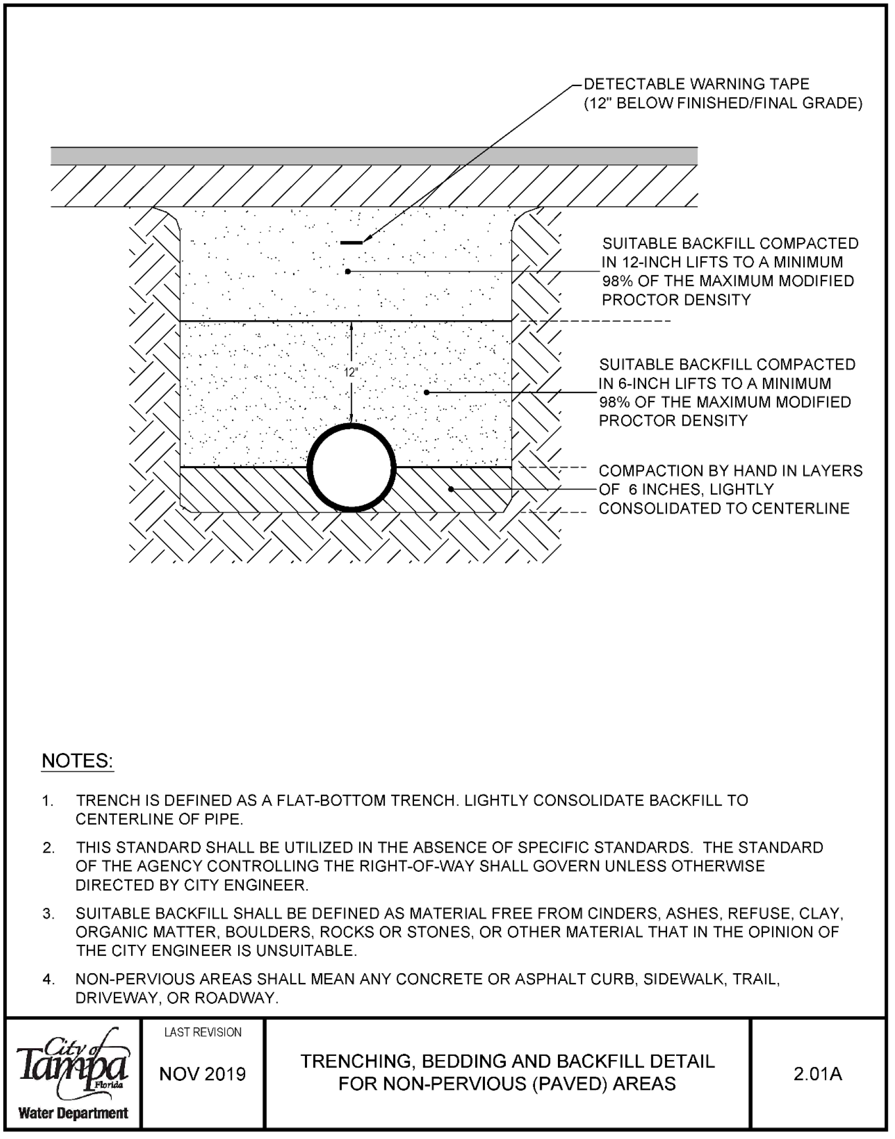
- DETECTABLE WARNING TAPE (12" BELOW FINISHED/FINAL GRADE)
- SUITABLE BACKFILL COMPACTED IN 12-INCH LIFTS TO A MINIMUM 98% OF THE MAXIMUM MODIFIED PROCTOR DENSITY
- SUITABLE BACKFILL COMPACTED IN 6-INCH LIFTS TO A MINIMUM 98% OF THE MAXIMUM MODIFIED PROCTOR DENSITY
- COMPACTION BY HAND IN LAYERS OF 6 INCHES, LIGHTLY CONSOLIDATED TO CENTERLINE
- TRENCH IS DEFINED AS A FLAT-BOTTOM TRENCH. LIGHTLY CONSOLIDATE BACKFILL TO CENTERLINE OF PIPE.
- THIS STANDARD SHALL BE UTILIZED IN THE ABSENCE OF SPECIFIC STANDARDS. THE STANDARD OF THE AGENCY CONTROLLING THE RIGHT-OF-WAY SHALL GOVERN UNLESS OTHERWISE DIRECTED BY CITY ENGINEER.
- SUITABLE BACKFILL SHALL BE DEFINED AS MATERIAL FREE FROM CINDERS, ASHES, REFUSE, CLAY, ORGANIC MATTER, BOULDERS, ROCKS OR STONES, OR OTHER MATERIAL THAT IN THE OPINION OF THE CITY ENGINEER IS UNSUITABLE.
- NON-PERVIOUS AREAS SHALL MEAN ANY CONCRETE OR ASPHALT CURB, SIDEWALK, TRAIL, DRIVEWAY, OR ROADWAY.
Water Department
LAST REVISION NOV 2019
TRENCHING, BEDDING AND BACKFILL DETAIL FOR NON-PERVIOUS (PAVED) AREAS 2.01A
Trenching, Bedding and Backfill Detail for Non-Pervious (Paved) Areas 2.01B
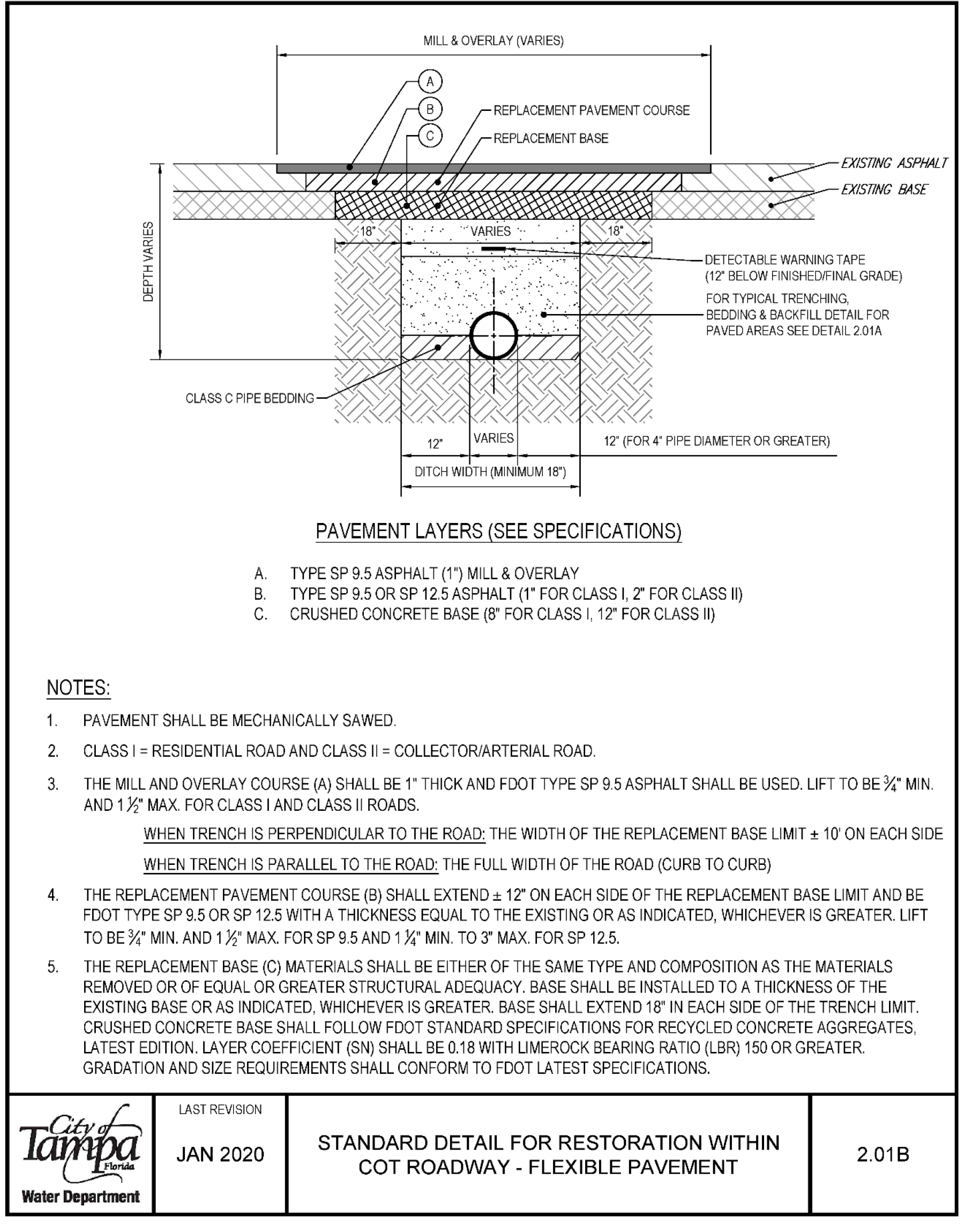
- NOTES: MILL & OVERLAY (VARIES) REPLACEMENT PAVEMENT COURSE
- EXISTING ASPHALT
- EXISTING BASE
- WARNING TAPE (12 BELOW FINISHED/FINAL GRADE) FOR TYPICAL TRENCHING
- BEDDING & BACKFILL DETAIL FOR PAVED AREAS SEE DETAIL 201A
- CLASS C PIPE BEDDING
- 12 VARIES 12" (FOR 4" PIPE DIAMETER OR GREATER) DITCH WIDTH (MINIMUM 18")
- PAVEMENT LAYERS (SEE SPECIFICATIONS)
- A. TYPE SP 9.5 ASPHALT (1") MILL & OVERLAY
- B. TYPE SP 9.5 OR SP 12.5 ASPHALT (1 FOR CLASS I, 2" FOR CLASS II)
- C. CRUSHED CONCRETE BASE (8" FOR CLASS I, 12" FOR CLASS II)
- 1. PAVEMENT SHALL BE MECHANICALLY SAWED.
- 2. CLASS I= RESIDENTIAL ROAD AND CLASS II= COLLECTOR/ARTERIAL ROAD.
- 3. THE MILLAND OVERLAY COURSE (A) SHALL BE 1 THICK AND FOOT TYPE SP 9.5 ASPHALT SHALL BE USED. LIFT TO BE %" MIN. AND 1 %" MAX. FOR CLASS I AND CLASS II ROADS. WHEN TRENCH IS PERPENDICULAR TO THE ROAD: THE WIDTH OF THE REPLACEMENT BASE LIMIT ± 10' ON EACH SIDE WHEN TRENCH IS PARALLEL TO THE ROAD: THE FULL WIDTH OF THE ROAD (CURB TO CURB)
- 4. THE REPLACEMENT PAVEMENT COURSE (B) SHALL EXTEND± 12" ON EACH SIDE OF THE REPLACEMENT BASE LIMIT AND BE FOOT TYPE SP 9.5 OR SP 12.5 WITH A THICKNESS EQUAL TO THE EXISTING OR AS INDICATED, WHICHEVER IS GREATER. LIFT TO BE %" MIN. AND 1 %" MAX. FOR SP 9.5 AND 1 %" MIN. TO 3" MAX. FOR SP 12.5.
- 5. THE REPLACEMENT BASE (C) MATERIALS SHALL BE EITHER OF THE SAME TYPE AND COMPOSITION AS THE MATERIALS REMOVED OR OF EQUAL OR GREATER STRUCTURAL ADEQUACY. BASE SHALL BE INSTALLED TO A THICKNESS OF THE EXISTING BASE OR AS INDICATED, WHICHEVER IS GREATER. BASE SHALL EXTEND 18" IN EACH SIDE OF THE TRENCH LIMIT. CRUSHED CONCRETE BASE SHALL FOLLOW FOOT STANDARD SPECIFICATIONS FOR RECYCLED CONCRETE AGGREGATES, LATEST EDITION. LAYER COEFFICIENT (SN) SHALL BE 0.18 WITH LIMEROCK BEARING RATIO (LBR) 150 OR GREATER. GRADATION AND SIZE REQUIREMENTS SHALL CONFORM TO FOOT LATEST SPECIFICATIONS.
Water Department LAST REVISION JAN 2020 STANDARD DETAIL FOR RESTORATION WITHIN COT ROADWAY -FLEXIBLE PAVEMENT 2.01B
Trenching, Bedding and Backfill Detail for Pervious (Non-Paved) Areas 2.02
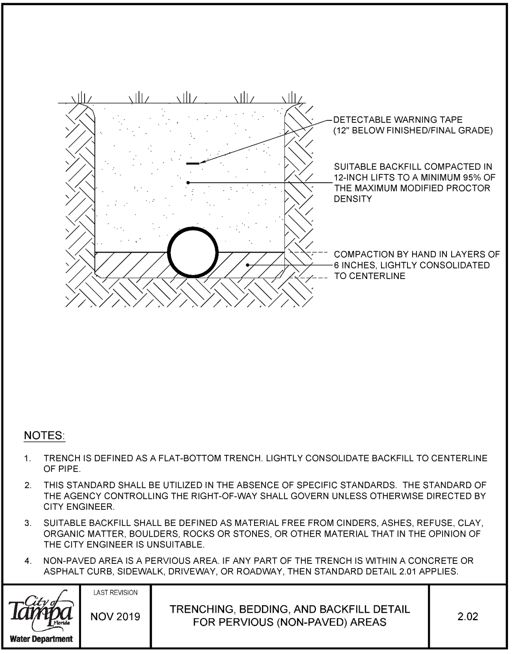
- DETECTABLE WARNING TAPE (12" BELOW FINISHED/FINAL GRADE)
- SUITABLE BACKFILL COMPACTED IN 12-INCH LIFTS TO A MINIMUM 95% OF THE MAXIMUM MODIFIED PROCTOR DENSITY
- COMPACTION BY HAND IN LAYERS OF 6 INCHES, LIGHTLY CONSOLIDATED
- 1. TRENCH IS DEFINED AS A FLAT-BOTTOM TRENCH. LIGHTLY CONSOLIDATE BACKFILL TO CENTERLINE OF PIPE.
- 2. THIS STANDARD SHALL BE UTILIZED IN THE ABSENCE OF SPECIFIC STANDARDS. THE STANDARD OF THE AGENCY CONTROLLING THE RIGHT-OF-WAY SHALL GOVERN UNLESS OTHERWISE DIRECTED BY CITY ENGINEER.
- 3. SUITABLE BACKFILL SHALL BE DEFINED AS MATERIAL FREE FROM CINDERS, ASHES, REFUSE, CLAY, ORGANIC MATTER, BOULDERS, ROCKS OR STONES, OR OTHER MATERIAL THAT IN THE OPINION OF THE CITY ENGINEER IS UNSUITABLE.
- 4. NON-PAVED AREA IS A PERVIOUS AREA. IF ANY PART OF THE TRENCH IS WITHIN A CONCRETE OR ASPHALT CURB, SIDEWALK, DRIVEWAY, OR ROADWAY, THEN STANDARD DETAIL 2.01 APPLIES.
Water Department
LAST REVISION NOV 2019
TRENCHING, BEDDING, AND BACKFILL DETAIL FOR PERVIOUS (NON-PAVED) AREAS 2.02
Jacking & Boring for Pavement Crossing 2.03
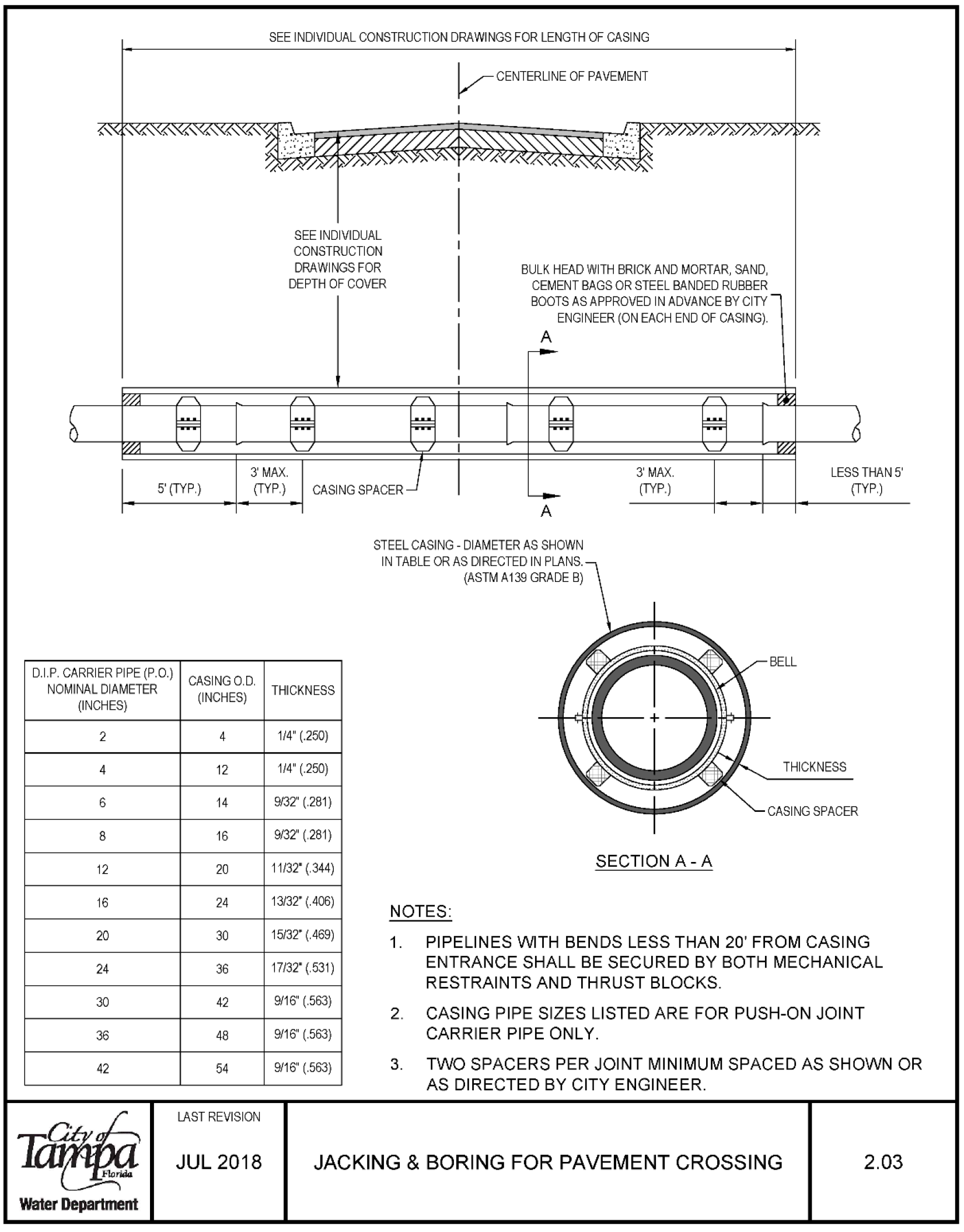
| D.I.P. CARRIER PIPE (P.O.) NOMINAL DIAMETER (INCHES) | 2 | 4 | 6 | 8 | 12 | 16 | 20 | 24 | 30 | 36 | 42 |
|---|---|---|---|---|---|---|---|---|---|---|---|
| Water Department CASING O.D (INCHES) | 4 | 12 | 14 | 16 | 20 | 24 | 30 | 36 | 42 | 48 | 54 |
| Steel Casing Thickness | |||||||||||
| Thickness (inches) | 1/4" (.250) | 1/4" (.250) | 9/32" (.281) | 9/32" (.281) | 11/32 (.344) | 13/32° (.406) | 15/32° (.469) | 17/32° (.531) | 9/16" (.563) | 9/16" (.563) | 9/16" (.563) |
- LAST REVISION JUL 2018
- SEE INDIVIDUAL CONSTRUCTION DRAWINGS FOR LENGTH OF CASING
- SEE INDIVIDUAL CONSTRUCTION DRAWINGS FOR DEPTH OF COVER
- VCENTERLINE OF PAVEMENT
- BULK HEAD WITH BRICK AND MORTAR, SAND, CEMENT BAGS OR STEEL BANDED RUBBER BOOTS AS APPROVED IN ADVANCE BY CITY ENGINEER (ON EACH END OF CASING).
- 3' MAX (TYP.)
- LESS THAN 5' (TYP.)
- STEEL CASING - DIAMETER AS SHOWN
- IN TABLE OR AS DIRECTED IN PLANS. (ASTM A139 GRADE B)
NOTES:
- PIPELINES WITH BENDS LESS THAN 20' FROM CASING ENTRANCE SHALL BE SECURED BY BOTH MECHANICAL RESTRAINTS AND THRUST BLOCKS.
- CASING PIPE SIZES LISTED ARE FOR PUSH-ON JOINT CARRIER PIPE ONLY.
- TWO SPACERS PER JOINT MINIMUM SPACED AS SHOWN OR AS DIRECTED BY CITY ENGINEER.
Jacking & Boring for Railroad Crossings 2.04
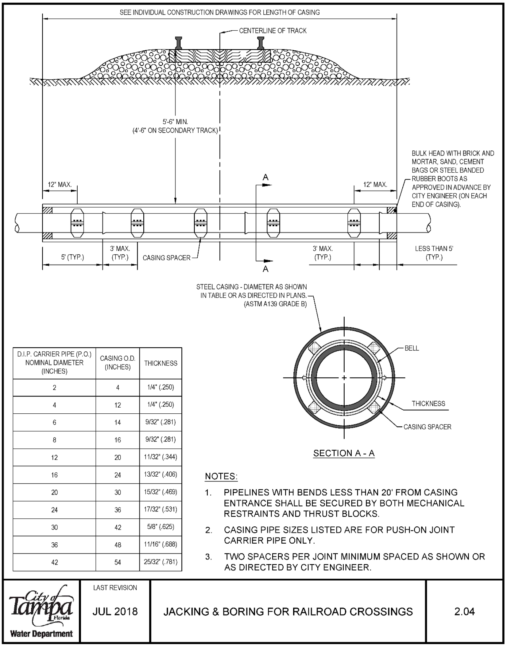
| Nominal Diameter (inches) | 2 | 4 | 6 | 8 | 12 | 16 | 20 | 24 | 30 | 36 | 42 |
|---|---|---|---|---|---|---|---|---|---|---|---|
| Casing O.D. (inches) | 4 | 12 | 14 | 16 | 20 | 24 | 30 | 36 | 42 | 48 | 54 |
| Thickness | 1/4" (.250) | 1/4" (.250) | 9/32" (.281) | 9/32" (.281) | 11/32" (.344) | 13/32" (.406) | 15/32" (.469) | 17/32" (.531) | 5/8" (.625) | 11/16" (.688) | 25/32" (.781) |
- SEE INDIVIDUAL CONSTRUCTION DRAWINGS FOR LENGTH OF CASING
- 5'-6" MIN. (4'-6" ON SECONDARY TRACK)
- BULK HEAD WITH BRICK AND MORTAR, SAND, CEMENT BAGS OR STEEL BANDED RUBBER BOOTS AS CASING
- STEEL CASING - DIAMETER AS SHOWN IN TABLE OR AS DIRECTED IN PLANS. (ASTM A139 GRADE B)
- 3' MAX. (TYP.) SECTION A-A LESS THAN 5' (TYP.)
- PIPELINES WITH BENDS LESS THAN 20' FROM CASING ENTRANCE SHALL BE SECURED BY BOTH MECHANICAL RESTRAINTS AND THRUST BLOCKS.
- CASING PIPE SIZES LISTED ARE FOR PUSH-ON JOINT CARRIER PIPE ONLY.
- TWO SPACERS PER JOINT MINIMUM SPACED AS SHOWN OR AS DIRECTED BY CITY ENGINEER.
Last revision Jul 2018
Polyethylene Encasement Installation Detail 2.05
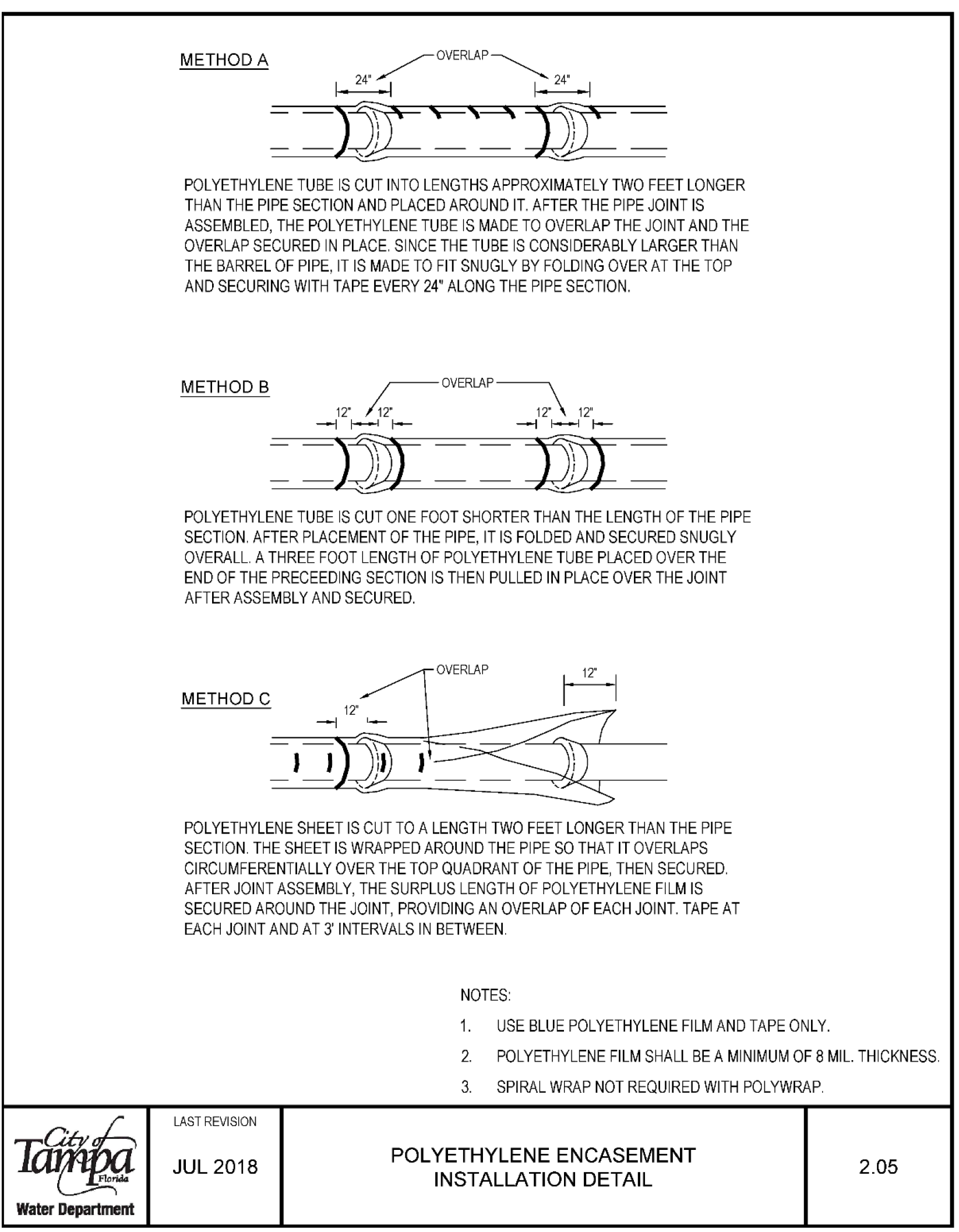
Water Department
METHOD A
POLYETHYLENE TUBE IS CUT INTO LENGTHS APPROXIMATELY TWO FEET LONGER THAN THE PIPE SECTION AND PLACED AROUND IT. AFTER THE PIPE JOINT IS ASSEMBLED, THE POLYETHYLENE TUBE IS MADE TO OVERLAP THE JOINT AND THE OVERLAP SECURED IN PLACE. SINCE THE TUBE IS CONSIDERABLY LARGER THAN THE BARREL OF PIPE, IT IS MADE TO FIT SNUGLY BY FOLDING OVER AT THE TOP AND SECURING WITH TAPE EVERY 24" ALONG THE PIPE SECTION.
METHOD B
POLYETHYLENE TUBE IS CUT ONE FOOT SHORTER THAN THE LENGTH OF THE PIPE SECTION. AFTER PLACEMENT OF THE PIPE, IT IS FOLDED AND SECURED SNUGLY OVERALL. A THREE FOOT LENGTH OF POLYETHYLENE TUBE PLACED OVER THE END OF THE PRECEEDING SECTION IS THEN PULLED IN PLACE OVER THE JOINT AFTER ASSEMBLY AND SECURED.
METHOD C
POLYETHYLENE SHEET IS CUT TO A LENGTH TWO FEET LONGER THAN THE PIPE SECTION. THE SHEET IS WRAPPED AROUND THE PIPE SO THAT IT OVERLAPS CIRCUMFERENTIALLY OVER THE TOP QUADRANT OF THE PIPE, THEN SECURED. AFTER JOINT ASSEMBLY, THE SURPLUS LENGTH OF POLYETHYLENE FILM IS SECURED AROUND THE JOINT, PROVIDING AN OVERLAP OF EACH JOINT TAPE AT EACH JOINT AND AT 3' INTERVALS IN BETWEEN.
NOTES
- USE BLUE POLYETHYLENE FILM AND TAPE ONLY.
- POLYETHYLENE FILM SHALL BE A MINIMUM OF 8 MIL THICKNESS LAST REVISION JUL 2018
- SPIRAL WRAP NOT REQUIRED WITH POLYWRAP.
Reinforced Concrete Shock Pad (For Cover Less Than 2.5') 2.06
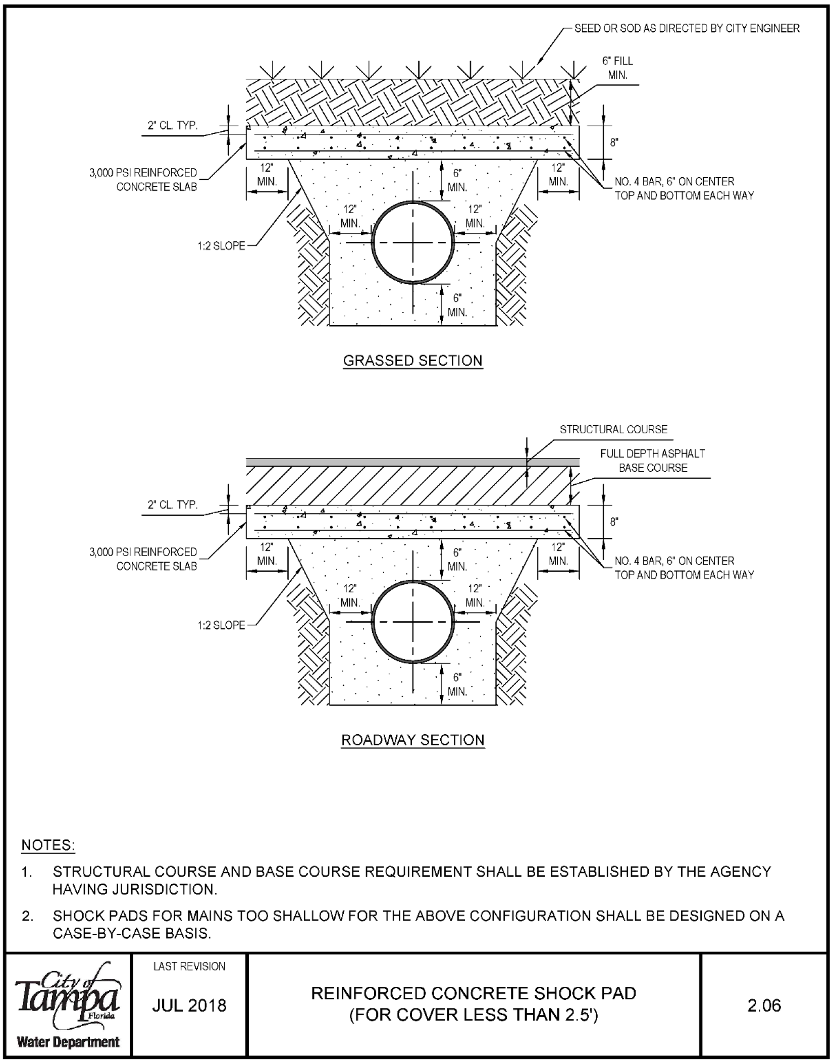
- 3,000 PSI REINFORCED CONCRETE SLAB 2 CL. TYP.
- 3,000 PSI REINFORCED CONCRETE SLAB 1 2 SLOPE 1:2 SLOPE
- GRASSED SECTION
- ROADWAY SECTION
- SEED OR SOD AS DIRECTED BY CITY ENGINEER
- 6FILL
- 8' NO. 4 BAR, 6" ON CENTER TOP AND BOTTOM EACH WAY
- STRUCTURAL COURSE
- FULL DEPTH ASPHALT BASE COURSE
- 8' NO. 4 BAR, 6" ON CENTER TOP AND BOTTOM EACH WAY
- STRUCTURAL COURSE AND BASE COURSE REQUIREMENT SHALL BE ESTABLISHED BY THE AGENCY HAVING JURISDICTION.
- SHOCK PADS FOR MAINS TOO SHALLOW FOR THE ABOVE CONFIGURATION SHALL BE DESIGNED ON A CASE-BY-CASE BASIS.
Water Department
LAST REVISION JUL 2018
REINFORCED CONCRETE SHOCK PAD (FOR COVER LESS THAN 2.5') 2.06
Restrained Joint Standard for Bends, Plugs, Caps, and Valves 2.11
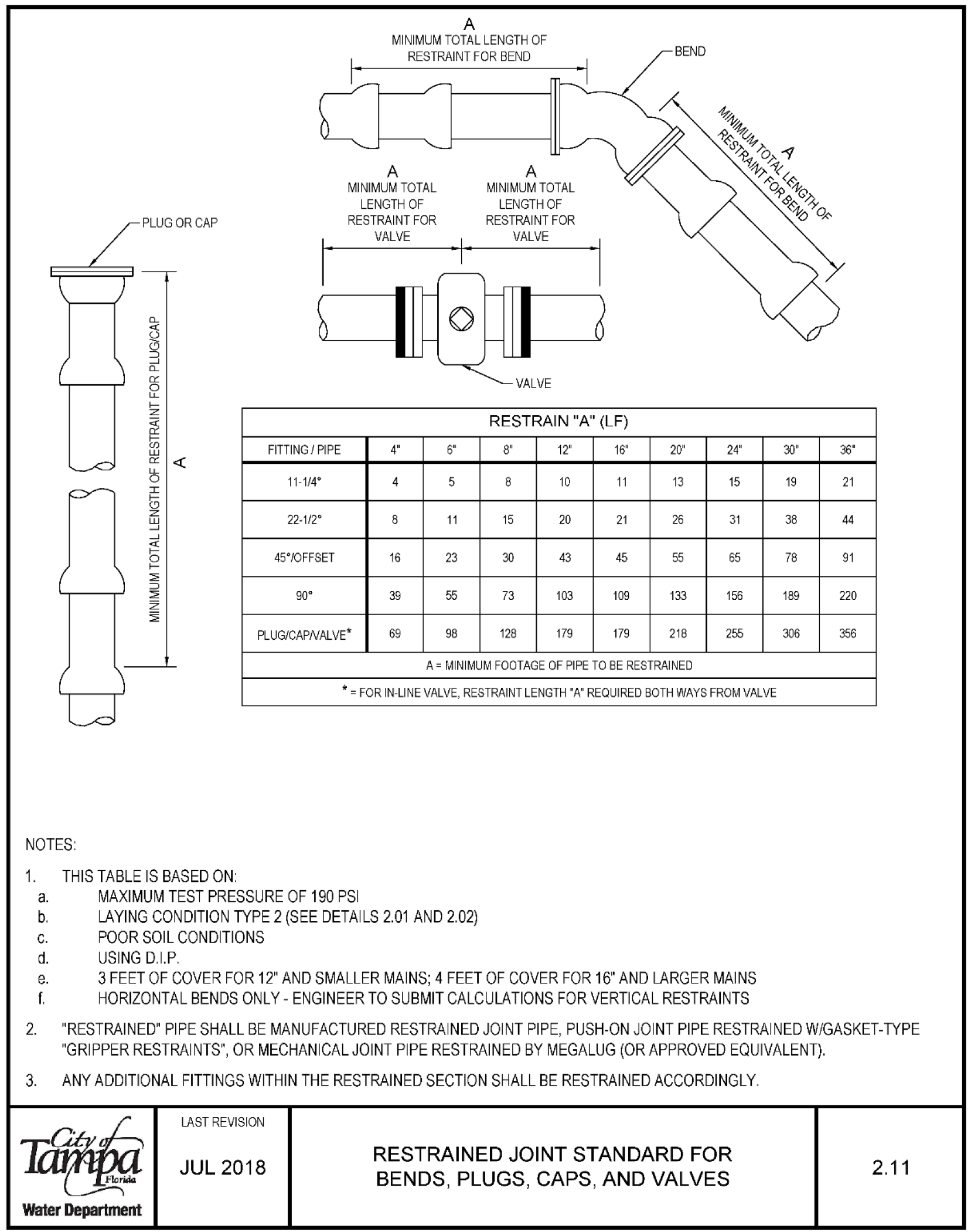
| Fitting / Pipe | 11-1/4° | 22-1/2° | 45°/Offset | 90° |
|---|---|---|---|---|
| Bend 4" | 4 | 6 | 8 | 12 |
| Bend 6" | 5 | 8 | 10 | 11 |
| Bend 8" | 8 | 11 | 15 | 20 |
| Bend 12" | 16 | 23 | 30 | 43 |
| Bend 16" | 21 | 39 | 55 | 73 |
| Bend 20" | 45 | 55 | 65 | 103 |
| Bend 24" | 109 | 133 | 156 | |
| Plug/Cap/Valve* | ||||
| 4" | 69 | 98 | 128 | 179 |
| 6" | 179 | 218 | 255 | |
| 8" | 30" | 36 | 19 | 21 |
| 12" | 38 | 44 | 78 | 91 |
| 16" | 189 | 220 | 306 | 356 |
- A = MINIMUM FOOTAGE OF PIPE TO BE RESTRAINED
- For in-line valve, restraint length "A" required both ways from valve
- This table is based on:
- Maximum test pressure of 190 PSI
- Laying condition type 2 (see details 2.01 and 2.02)
- Poor soil conditions using D.I.P.
- 3 feet of cover for 12" and smaller mains; 4 feet of cover for 16" and larger mains
- Horizontal bends only - engineer to submit calculations for vertical restraints
- "Restrained" pipe shall be manufactured restrained joint pipe, push-on joint pipe restrained with gasket-type "gripper restraints", or mechanical joint pipe restrained by Megalug (or approved equivalent).
- Any additional fittings within the restrained section shall be restrained accordingly.
Water Department
Last revision Jul 2018
Restrained Joint Standard for Bends, Plugs, Caps, and Valves 2.11
Restrained Joint Standard for Tees and Reducers 2.12A
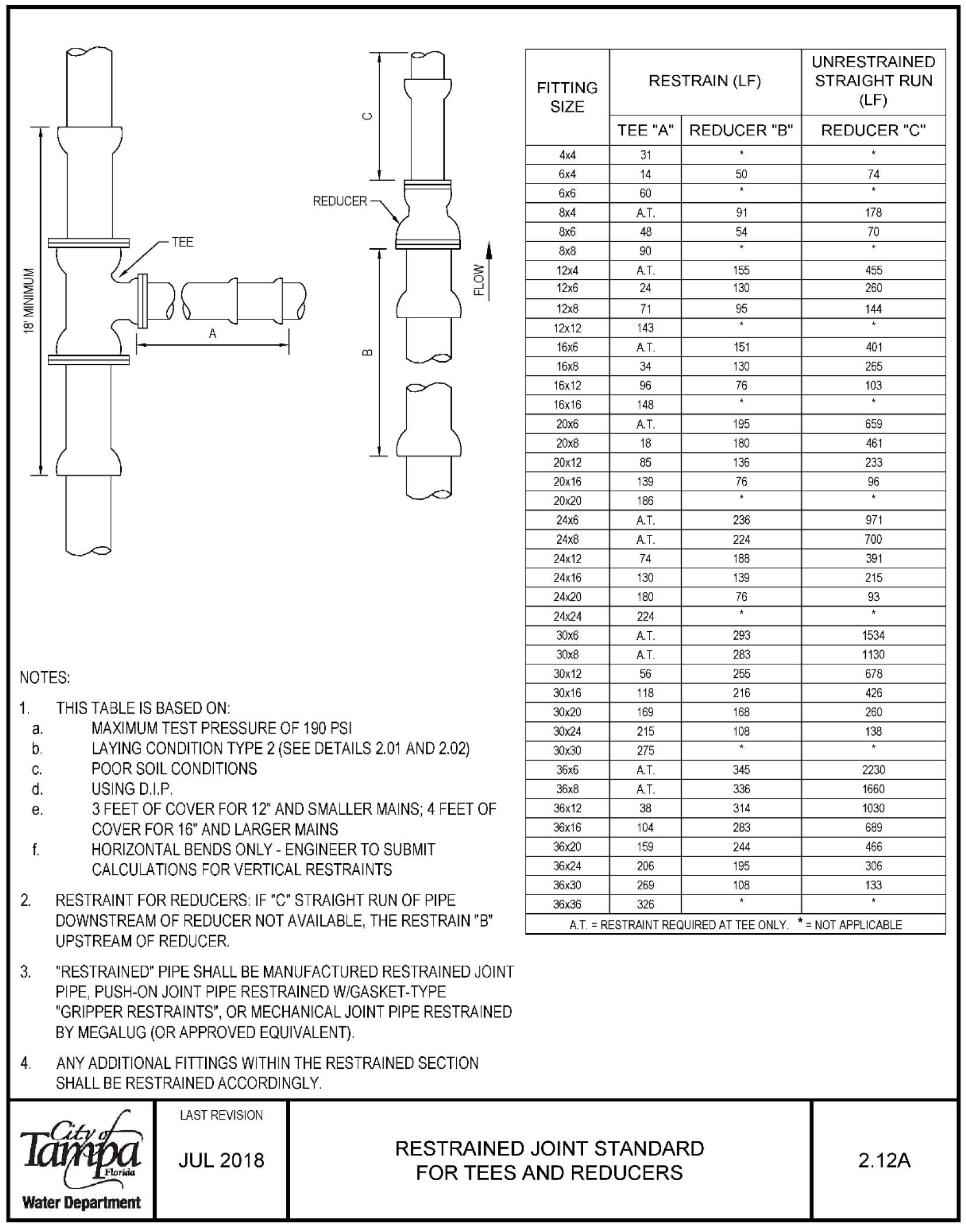
| Size | Unrestrained Fitting | Restrain (LF) | Straight Run Size (LF) | Tee "A" | Reducer "B" | Reducer "C" |
|---|---|---|---|---|---|---|
| 4x4 | 31 | |||||
| 6x4 | 14 | 50 | 74 | |||
| 6x6 | 60 | |||||
| 8x4 A.T. | 91 | 178 | ||||
| 8x6 | 48 | 54 | 70 | |||
| 8x8 | 90 | |||||
| 12x4 A.T. | 155 | 455 | ||||
| 12x6 | 24 | 130 | 260 | |||
| 12x8 | 71 | 95 | 144 | |||
| 12x12 | 143 | |||||
| 16x6 AT. | 151 | 401 | ||||
| 16x8 | 34 | 130 | 265 | |||
| 16x12 | 96 | 76 | 103 | |||
| 16x16 | 148 | |||||
| 20x6 A.T. | 195 | 659 | ||||
| 20x8 | 18 | 180 | 461 | |||
| 20x12 | 85 | 136 | 233 | |||
| 20x16 | 139 | 76 | 96 | |||
| 20x20 | 186 | |||||
| 24x6 A.T. | 236 | 971 | ||||
| 24x8 A.T. | 224 | 700 | ||||
| 24x12 | 74 | 188 | 391 | |||
| 24x16 | 130 | 139 | 215 | |||
| 24x20 | 180 | 76 | 93 | |||
| 24x24 | 224 | |||||
| 30x6 A.T. | 293 | 1534 | ||||
| 30x8 A.T. | 283 | 1130 | ||||
| 30x12 | 56 | 255 | 678 | |||
| 30x16 | 118 | 216 | 426 | |||
| 30x20 | 169 | 168 | 260 | |||
| 30x24 | 215 | 108 | 138 | |||
| 30x30 | 275 | |||||
| 36x6 A.T. | 345 | 2230 | ||||
| 36x8 A.T. | 336 | 1660 | ||||
| 36x12 | 38 | 314 | 1030 | |||
| 36x16 | 104 | 283 | 689 | |||
| 36x20 | 159 | 244 | 466 | |||
| 36x24 | 206 | 195 | 306 | |||
| 36x30 | 269 | 108 | 133 | |||
| 36x36 | 326 |
- NOTES:
- 1. THIS TABLE IS BASED ON:
- a. MAXIMUM TEST PRESSURE OF 190 PSI
- b. LAYING CONDITION TYPE 2 (SEE DETAILS 2.01 AND 2.02)
- c. POOR SOIL CONDITIONS
- d. USING D.I.P.
- e. 3 FEET OF COVER FOR 12 AND SMALLER MAINS; 4 FEET OF COVER FOR 16" AND LARGER MAINS
- f. HORIZONTAL BENDS ONLY - ENGINEER TO SUBMIT CALCULATIONS FOR VERTICAL RESTRAINTS
- 2. RESTRAINT FOR REDUCERS IF "C" STRAIGHT RUN OF PIPE DOWNSTREAM OF REDUCER NOT AVAILABLE, THE RESTRAIN "B" A.T. = RESTRAINT REQUIRED AT TEE ONLY. * NOT APPLICABLE UPSTREAM OF REDUCER
- 3. "RESTRAINED" PIPE SHALL BE MANUFACTURED RESTRAINED JOINT PIPE, PUSH-ON JOINT PIPE RESTRAINED W/GASKET-TYPE "GRIPPER RESTRAINTS", OR MECHANICAL JOINT PIPE RESTRAINED BY MEGALUG (OR APPROVED EQUIVALENT).
- 4. ANY ADDITIONAL FITTINGS WITHIN THE RESTRAINED SECTION SHALL BE RESTRAINED ACCORDINGLY
LAST REVISION JUL 2018
RESTRAINED JOINT STANDARD 2.12A FOR TEES AND REDUCERS
Water Department
Deadman Thrust Block 2.12B
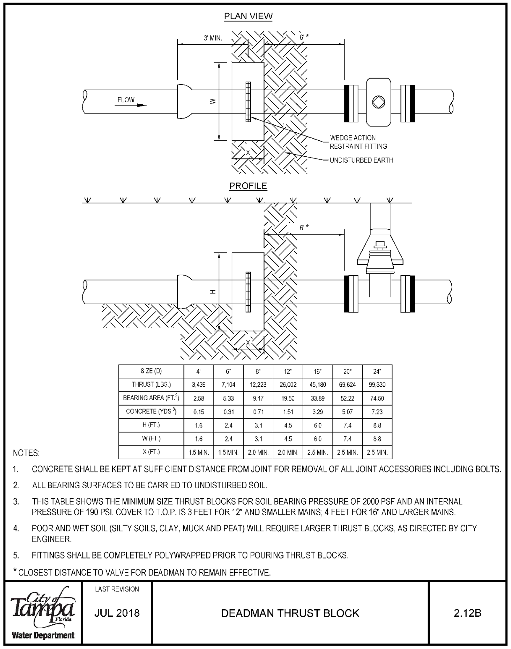
| FLOW SIZE (Ø) | THRUST (LBS.) | BEARING AREA (FT²) | CONCRETE (YDS³) | H (FT.) | W (FT.) |
|---|---|---|---|---|---|
| 4 | 3,439 | 2.58 | 0.15 | 1.6 | 1.6 |
| 6 | 7,104 | 3.89 | 0.31 | 2.4 | 2.4 |
| 8 | 12,223 | 6.11 | 0.71 | 3.1 | 3.1 |
| 12 | 26,002 | 13.00 | 1.51 | 4.5 | 4.5 |
| 16 | 45,180 | 22.59 | 3.29 | 6.0 | 6.0 |
| 20 | 69,624 | 34.81 | 5.07 | 7.4 | 7.4 |
| 24 | 99,330 | 49.67 | 7.23 | 8.8 | 8.8 |
- CONCRETE SHALL BE KEPT AT SUFFICIENT DISTANCE FROM JOINT FOR REMOVAL OF ALL JOINT ACCESSORIES INCLUDING BOLTS
- ALL BEARING SURFACES TO BE CARRIED TO UNDISTURBED SOIL
- THIS TABLE SHOWS THE MINIMUM SIZE THRUST BLOCKS FOR SOIL BEARING PRESSURE OF 2000 PSF AND AN INTERNAL PRESSURE OF 190 PSI. COVER TO T.O.P. IS 3 FEET FOR 12" AND SMALLER MAINS; 4 FEET FOR 16" AND LARGER MAINS.
- POOR AND WET SOIL (SILTY SOILS, CLAY, MUCK AND PEAT) WILL REQUIRE LARGER THRUST BLOCKS, AS DIRECTED BY CITY ENGINEER.
- FITTINGS SHALL BE COMPLETELY POLYWRAPPED PRIOR TO POURING THRUST BLOCKS.
- * CLOSEST DISTANCE TO VALVE FOR DEADMAN TO REMAIN EFFECTIVE.
LAST REVISION JUL 2018
DEADMANTHRUSTBLOCK
Water Department 2.12B
Tapped Connection from DI, Cl, or PVC Pipe to <4" Water Mains 2.13A
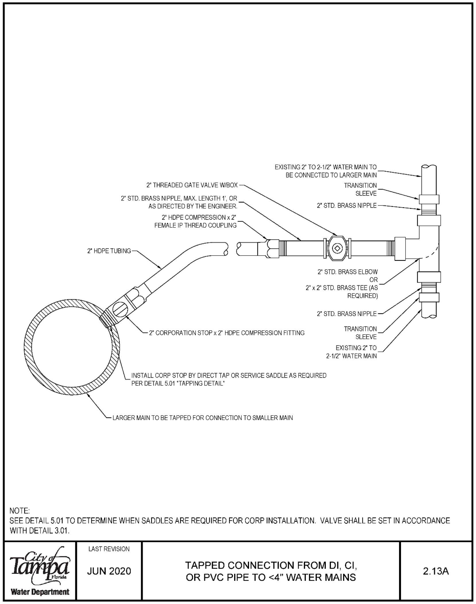
NOTE EXISTING 2 TO 2-1/2° WATER MAIN TO BE CONNECTED TO LARGER MAIN 2' THREADED GATE VALVE WIBOX 2 STD, BRASS NIPPLE, MAX. LENGTH 1, OR AS DIRECTED BY THE ENGINEER. 2 HDPETUBING 2 CORPORATION STOPx2 HOPE COMPRESSION FITTING INSTALL CORP STOP BY DIRECT TAP OR SERVICE SADDLE AS REQUIRED PER DETAIL 5.01 "TAPPING DETAIL' LARGER MAIN TO BE TAPPED FOR CONNECTION TO SMALLER MAIN EXISTING 2 TO 2-1/2" WATER MAIN SEE DETAIL 5 01 TO DETERMINE WHEN SADDLES ARE REQUIRED FOR CORP INSTALLATION VALVE SHALL BE SET IN ACCORDANCE WITH DETAIL 3.01. Water Department LAST REVISION JUN 2020 TAPPED CONNECTION FROM DI, Cl, OR PVC PIPE TO <4" WATER MAINS 2.13A
Tapped Connection for <4" Water Main to HDPE Water Main 2.13B
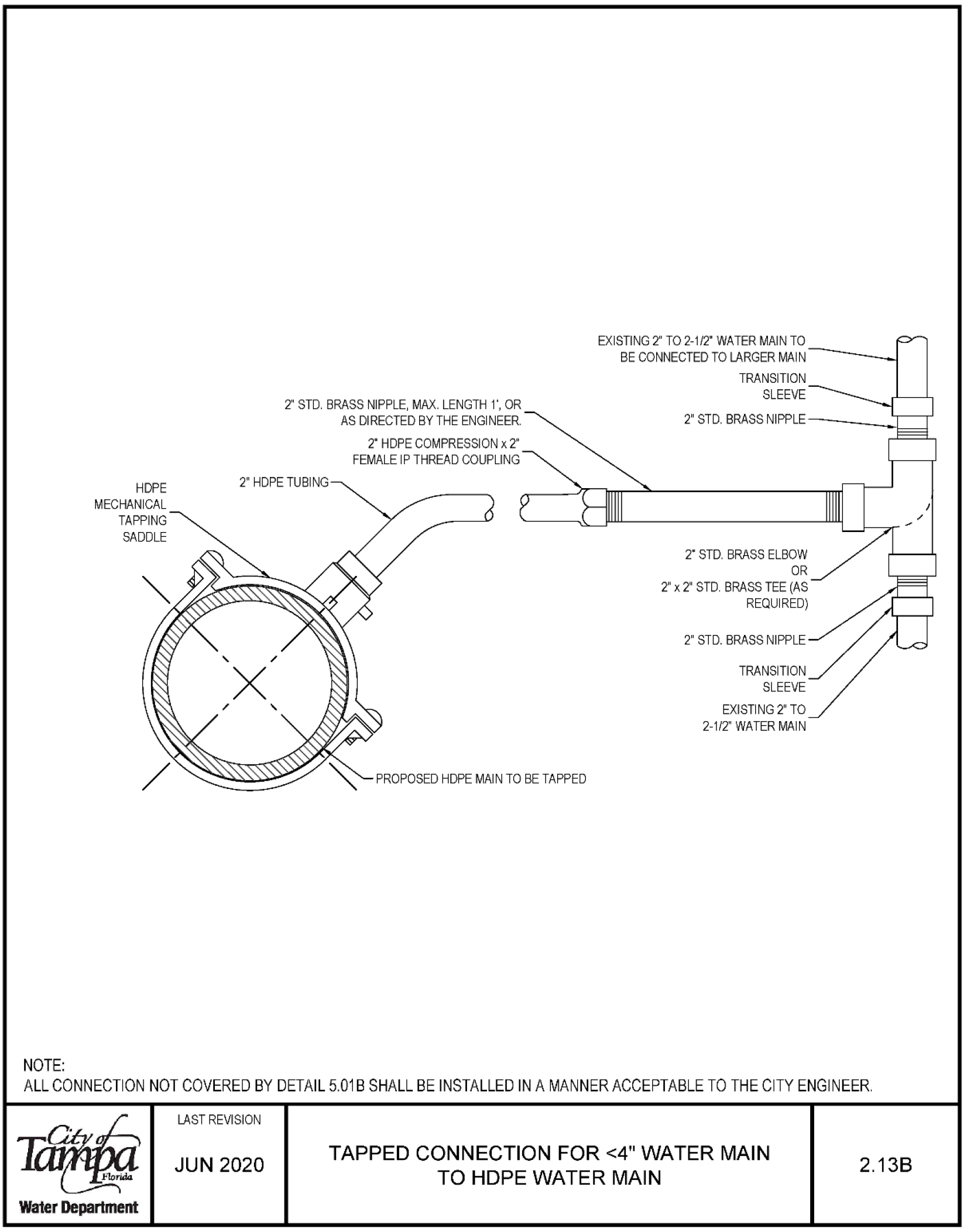
NOTE: HDPE MECHANICAL TAPPING SADDLE 2 STD, BRASS NIPPLE, MAX. LENGTH I', OR AS DIRECTED BY THE ENGINEER 2' HDPE TUBING 2 HDPE COMPRESSION x 2 FEMALE IP THREAD COUPLING Ł PROPOSED HDPE MAIN TO BE TAPPED EXISTING 2 TO 2-1/2° WATER MAIN TO BE CONNECTED TO LARGER MAIN TRANSITION SLEEVE 2° STD. BRASS ELBOW OR 2" x 2" STD. BRASS TEE (AS REQUIRED) 2 STD BRASS NIPPLE TRANSITION SLEEVE EXISTING 2 TO 2-1/2" WATER MAIN ALL CONNECTION NOT COVERED BY DETAIL 5.01 B SHALL BE INSTALLED IN A MANNER ACCEPTABLE TO THE CITY ENGINEER Water Department LAST REVISION JUN 2020 TAPPED CONNECTION FOR <4" WATER MAIN TO HDPE WATER MAIN 2.138
Automatic Air Release Valve 2.14A
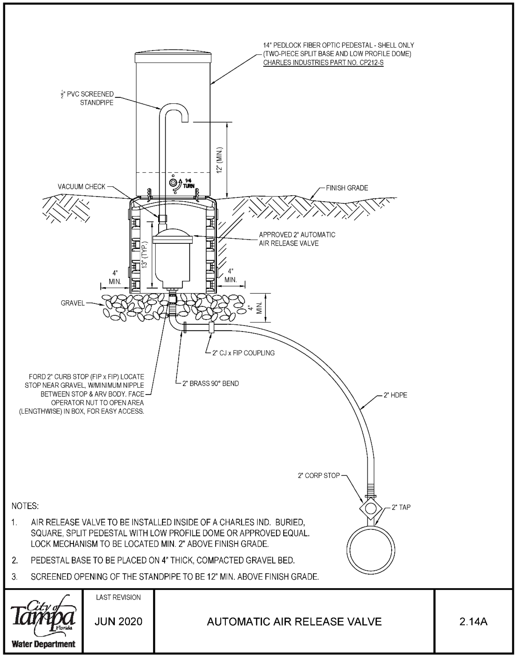
14" PEDLOCK FIBER OPTIC PEDESTAL· SHELL ONLY (TWO-PIECE SPLIT BASE AND LOW PROFILE DOME) CHARLES INDUSTRIES PART NO CP212 S Ł PVC SCREENED STANDPIPE FORD 2 CURB STOP (FIP x FIP) LOCATE STOP NEAR GRAVEL, W/MINIMUM NIPPLE BETWEEN STOP & ARV BODY FACE OPERATOR NUT TO OPEN AREA (LENGTHWISE) IN BOX, FOR EASY ACCESS.
- NOTES:
- 1. FINISH GRADE EX°ov«oz»vrowne I-AIR RELEASE VALVE 2 BRASS 90° BEND 2' CORP STOP 2' HDPE 2 TAP
- 2. AIR RELEASE VALVE TO BE INSTALLED INSIDE OF A CHARLES IND. BURIED, SQUARE, SPLIT PEDESTAL WITH LOW PROFILE DOME OR APPROVED EQUAL. LOCK MECHANISM TO BE LOCATED MIN. 2" ABOVE FINISH GRADE. PEDESTAL BASE TO BE PLACED ON 4 THICK, COMPACTED GRAVEL BED, 0
- 3. SCREENED OPENING OF THE STANDPIPE TO BE 12" MIN. ABOVE FINISH GRADE.
LAST REVISION JUN 2020
AUTOMATIC AIR RELEASE VALVE Water Department 2.14A
Automatic Air Release/Air Vacuum Valve 2.14B
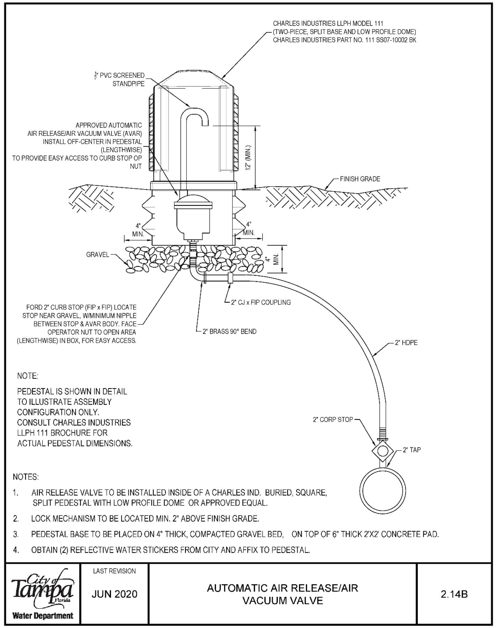
CHARLES INDUSTRIES LLPH MODEL 111 (TWO PIECE. SPUTBASE AND LOW PROFILE DOME) CHARLES INDUSTRIES PART NO 111 SS07 10002 BK APPROVED AUTOMATIC AIR RELEASE/AIR VACUUM VALVE (AVAR) INSTALL OFF-CENTER IN PEDESTAL (LENGTHWISE) TO PROVIDE EASY ACCESS TO CURB STOP OP NUT GRAVEL FORD 2 CURB STOP (FIP x FIP) LOCATE STOP NEAR GRAVEL, W/MINIMUM NIPPLE BETWEEN STOP & AVAR BODY FACE OPERATOR NUT TO OPEN AREA {LENGTHWISE) IN BOX, FOR EASY ACCESS. NOTE: PEDESTAL IS SHOWN IN DETAIL TO ILLUSTRATE ASSEMBLY CONFIGURATION ONLY. CONSULT CHARLES INDUSTRIES LLPH 111 BROCHURE FOR ACTUAL PEDESTAL DIMENSIONS. FINISH GRADE 2 HDPE 2 CORP STOP 2' TAP
- AIR RELEASE VALVE TO BE INSTALLED INSIDE OF A CHARLES IND. BURIED, SQUARE, SPLIT PEDESTAL WITH LOW PROFILE DOME OR APPROVED EQUAL.
- LOCK MECHANISM TO BE LOCATED MIN. 2 ABOVE FINISH GRADE.
- PEDESTAL BASE TO BE PLACED ON 4" THICK, COMPACTED GRAVEL BED, ON TOP OF 6" THICK 2'X2' CONCRETE PAD.
- OBTAIN (2) REFLECTIVE WATER STICKERS FROM CITY AND AFFIX TO PEDESTAL.
Water Department
LAST REVISION JUN 2020
AUTOMATIC AIR RELEASE/AIR VACUUM VALVE 2.14B
Blow-Off Valve Assembly for 24" Mains w/ DI, CI or PVC Pipe 2.17A
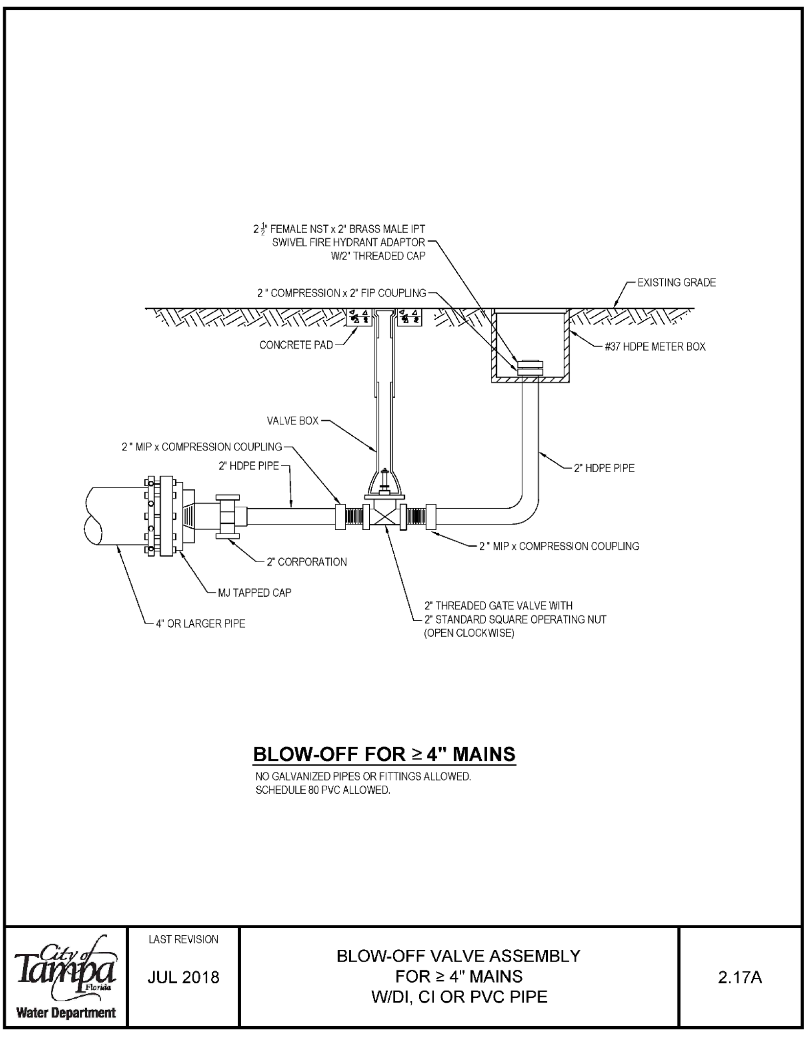
Water Department 2} FEMALE NST x 2 BRASS MALE IPT SWIVEL FIRE HYDRANT ADAPTOR W/2 THREADED CAP EXISTING GRADE #37 HOPE METER BOX VALVE BOX 2 " MIP x COMPRESSION COUPLING 2 HDPE PIPE -2" MIP x COMPRESSION COUPLING 2 CORPORATION MJ TAPPED CAP 4 OR LARGER PIPE LAST REVISION JUL 2018 2 THREADED GATE VALVE WITH 2 STANDARD SQUARE OPERATING NUT (OPEN CLOCKWISE) BLOW-OFF FOR > 4" MAINS NO GALVANIZED PIPES OR FITTINGS ALLOWED. SCHEDULE 80 PVC ALLOWED. BLOW-OFF VALVE ASSEMBLY FOR > 4" MAINS W/DI, Cl OR PVC PIPE 2.17A
Blow-Off Valve Assembly for 4" & 6" Mains w/ DI, Cl or PVC Pipe - Lateral Connection 2.17C
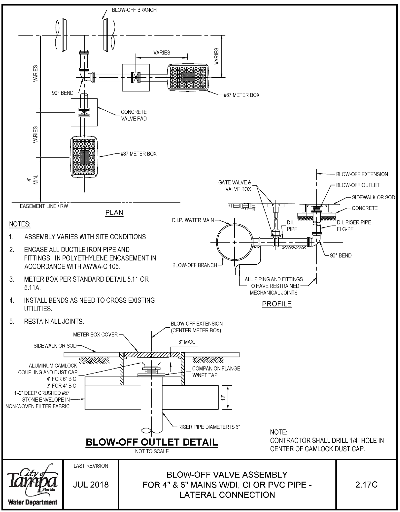
- ASSEMBLY VARIES WITH SITE CONDITIONS
- ENCASE ALL DUCTILE IRON PIPE AND FITTINGS IN POLYETHYLENE ENCASEMENT IN ACCORDANCE WITH AWWA-C 105.
- METER BOX PER STANDARD DETAIL 5.11 OR 5.11A.
- INSTALL BENDS AS NEED TO CROSS EXISTING UTILITIES.
- RESTAIN ALL JOINTS.
- ALL PIPING AND FITTINGS TO HAVE RESTRAINED MECHANICAL JOINTS.
- CONTRACTOR SHALL DRILL 1/4" HOLE IN CENTER OF CAMLOCK DUST CAP.
LAST REVISION JUL 2018
Temporary Sample Tap Installation w/ DI, Cl, or PVC Pipe 2.18A
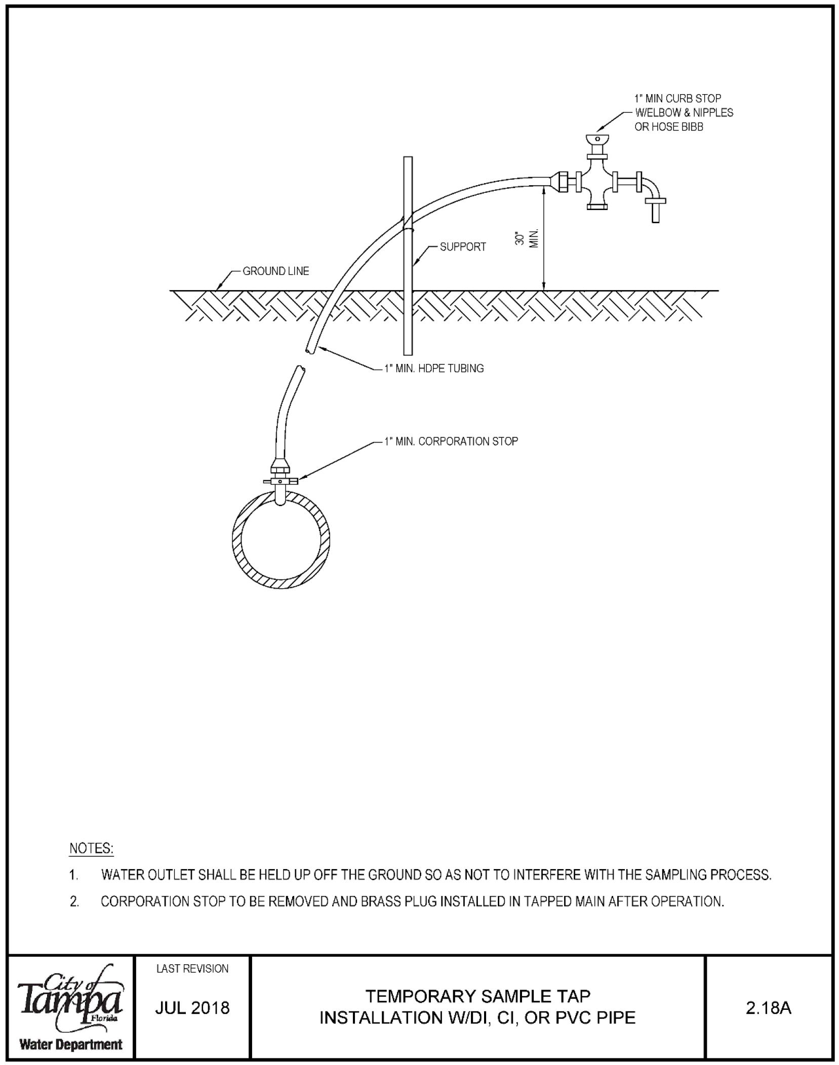
- 1 MIN CORPORATION STOP
- 1" MIN CURB STOP W/ELBOW & NIPPLES Ł OR HOSE BIBB
- 1. WATER OUTLET SHALL BE HELD UP OFF THE GROUND SO AS NOT TO INTERFERE WITH THE SAMPLING PROCESS,
- 2. CORPORATION STOP TO BE REMOVED AND BRASS PLUG INSTALLED IN TAPPED MAIN AFTER OPERATION,
Water Department
LAST REVISION JUL 2018
TEMPORARY SAMPLE TAP INSTALLATION W/DI, CI, OR PVC PIPE 2.18A
Temporary Sample Tap Installation for End of Line w/ DI, Cl, or PVC Pipe 2.19A
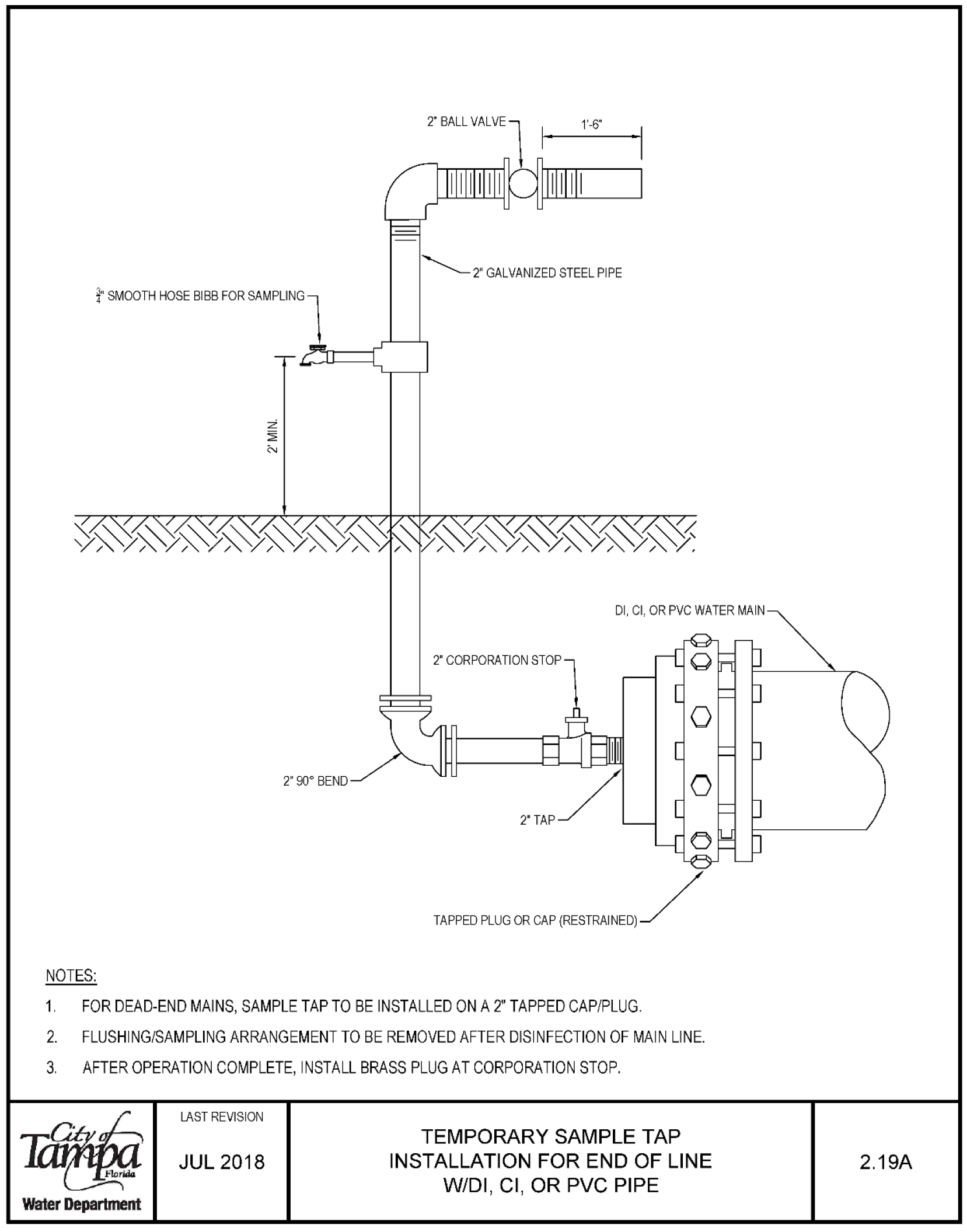
- 1'-6" SMOOTH HOSE BIBB FOR SAMPLING l DI, CI. OR PVC WATER MAIN
- 90° BEND TAPPED PLUG OR CAP (RESTRAINED)
NOTES:
- FOR DEAD-END MAINS, SAMPLE TAP TO BE INSTALLED ON A TAPPED CAP/PLUG.
- FLUSHING/SAMPLING ARRANGEMENT TO BE REMOVED AFTER DISINFECTION OF MAIN LINE.
- AFTER OPERATION COMPLETE, INSTALL BRASS PLUG AT CORPORATION STOP.
Water Department
LAST REVISION JUL 2018
TEMPORARY SAMPLE TAP INSTALLATION FOR END OF LINE W/DI, Cl, OR PVC PIPE 2.19A
Ductile Iron Pipe Identification Detail 2.20
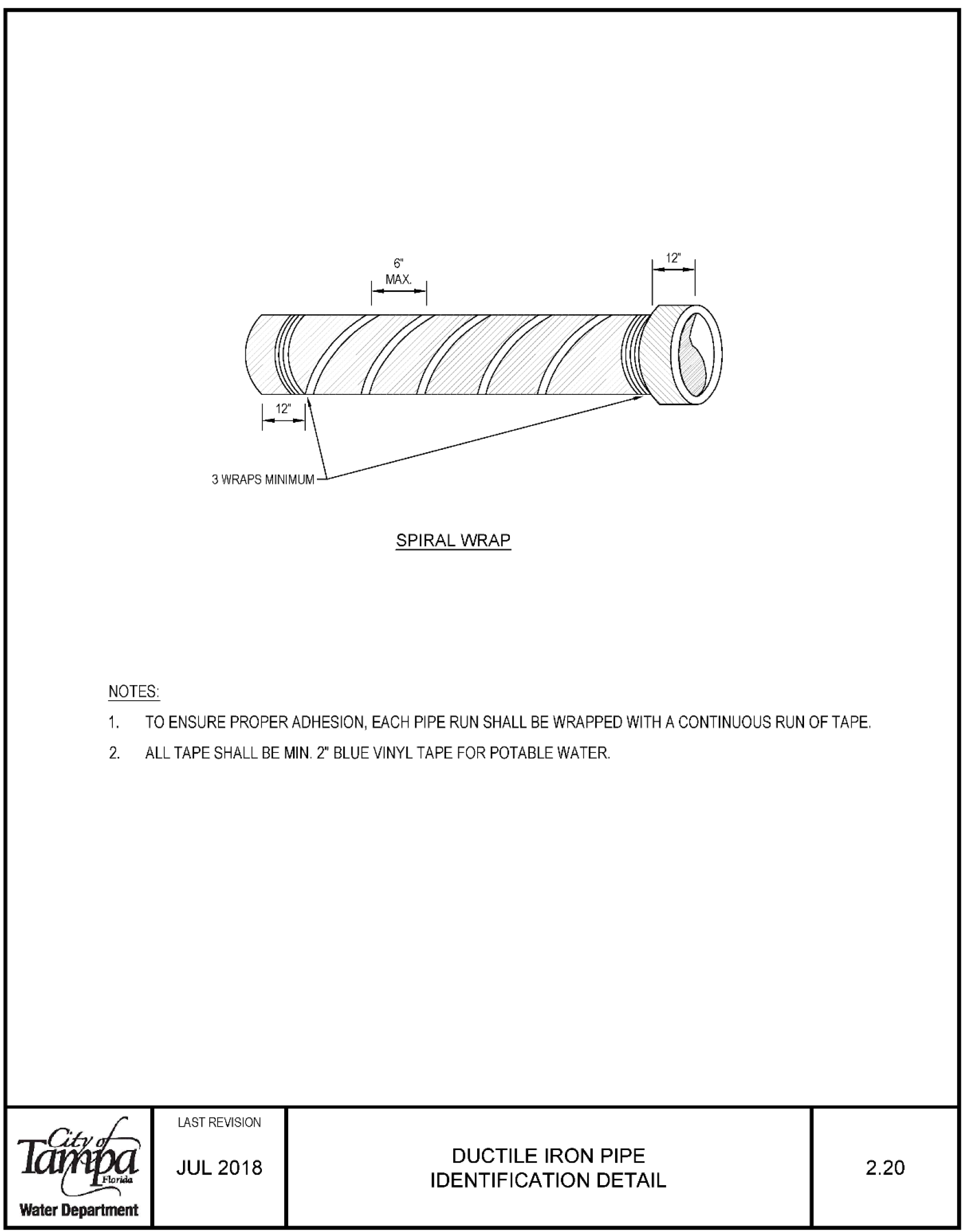
- SPIRAL WRAP NOTES:
- 1. TO ENSURE PROPER ADHESION, EACH PIPE RUN SHALL BE WRAPPED WITH A CONTINUOUS RUN OF TAPE.
- 2. ALL TAPE SHALL BE MIN. 2 BLUE VINYL TAPE FOR POTABLE WATER
Water Department
LAST REVISION JUL 2018
DUCTILE IRON PIPE IDENTIFICATION DETAIL 2.20
Valve Installation w/ Valve Box & Pad for DI or Cl Pipe 3.01
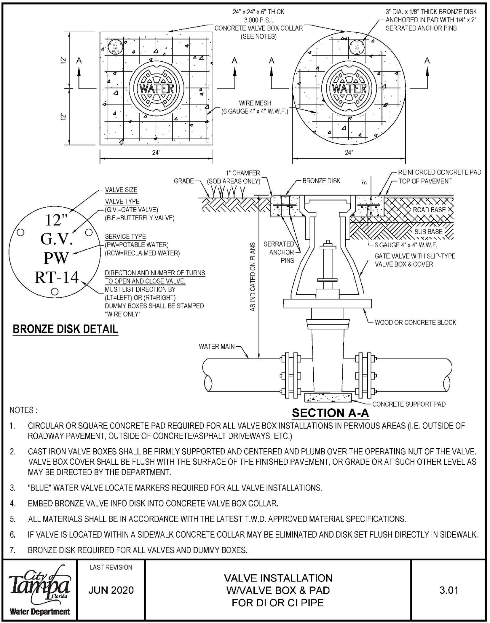
Notes:
- Circular or square concrete pad required for all valve box installations in pervious areas (i.e. outside of roadway pavement, outside of concrete/asphalt driveways, etc.)
- Cast iron valve boxes shall be firmly supported and centered and plumb over the operating nut of the valve. Valve box cover shall be flush with the surface of the finished pavement, or grade or at such other level as may be directed by the department.
- "Blue" water valve locate markers required for all valve installations.
- Embed bronze valve info disk into concrete valve box collar.
- All materials shall be in accordance with the latest T.W.D. approved material specifications.
- If valve is located within a sidewalk concrete collar may be eliminated and disk set flush directly in sidewalk.
- Bronze disk required for all valves and dummy boxes.
Water Department
Last Revision Jun 2020
VALVE INSTALLATION WNALVE BOX & PAD FOR DI OR Cl PIPE 3.01
Valve Installation w/ Valve Box & Pad for Plastic Pipe with Double Copper Tracer Wire on Pipe 3.02
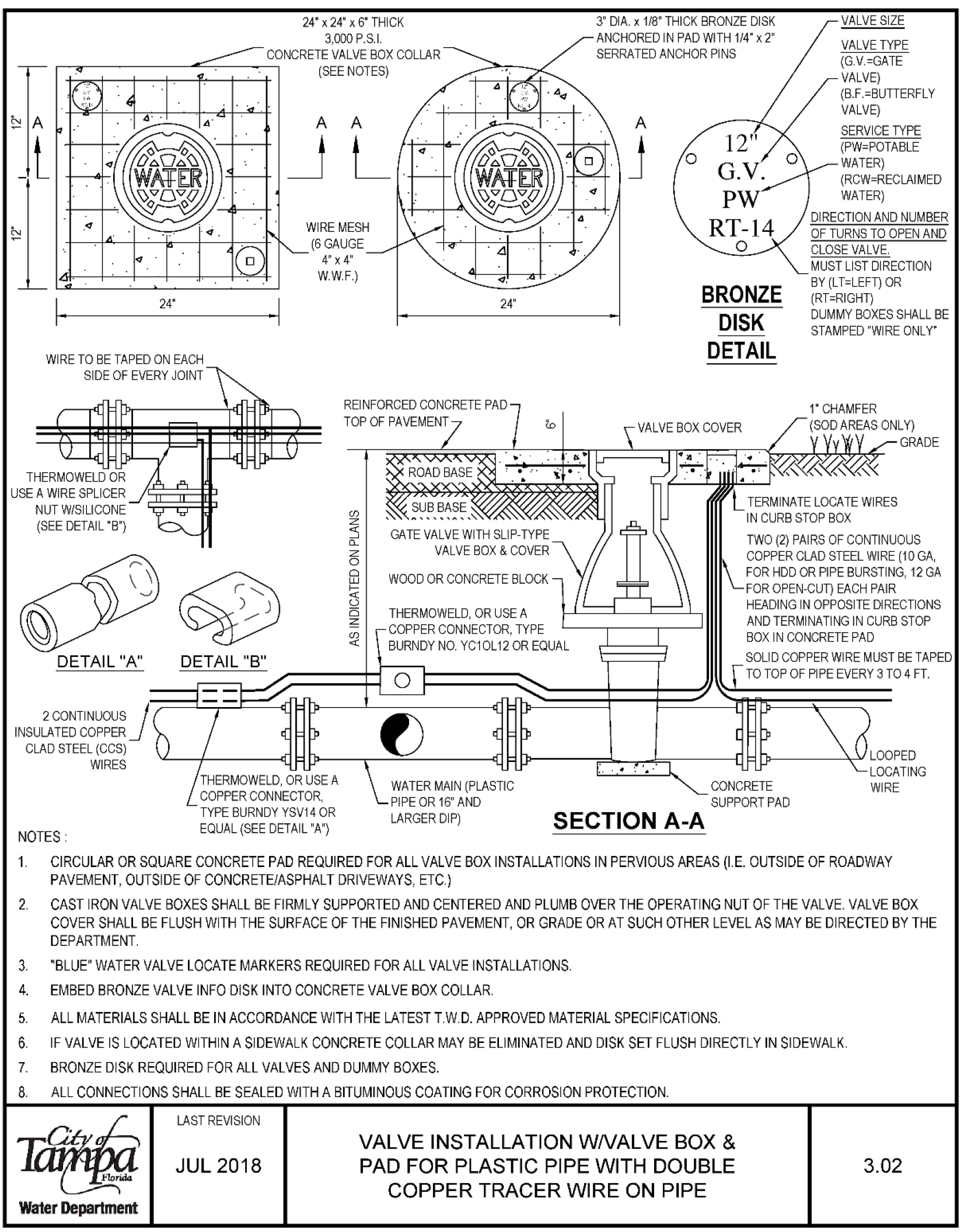
Notes
- Circular or square concrete pad required for all valve box installations in pervious areas (i.e. outside of roadway pavement, outside of concrete/asphalt driveways, etc)
- Cast iron valve boxes shall be firmly supported and centered and plumb over the operating nut of the valve. Valve box cover shall be flush with the surface of the finished pavement, or grade or at such other level as may be directed by the department.
- "Blue" water valve locate markers required for all valve installations.
- Embed bronze valve info disk into concrete valve box collar.
- All materials shall be in accordance with the latest T.W.D. approved material specifications.
- If valve is located within a sidewalk concrete collar may be eliminated and disk set flush directly in sidewalk.
- Bronze disk required for all valves and dummy boxes.
- All connections shall be sealed with a bituminous coating for corrosion protection.
Water Department
Last revision Jul 2018
VALVE INSTALLATION W/VALVE BOX & PAD FOR PLASTIC PIPE WITH DOUBLE COPPER TRACER WIRE ON PIPE 3.02
Plug (216") Valve Installation w/ Valve Box & Pad 3.03
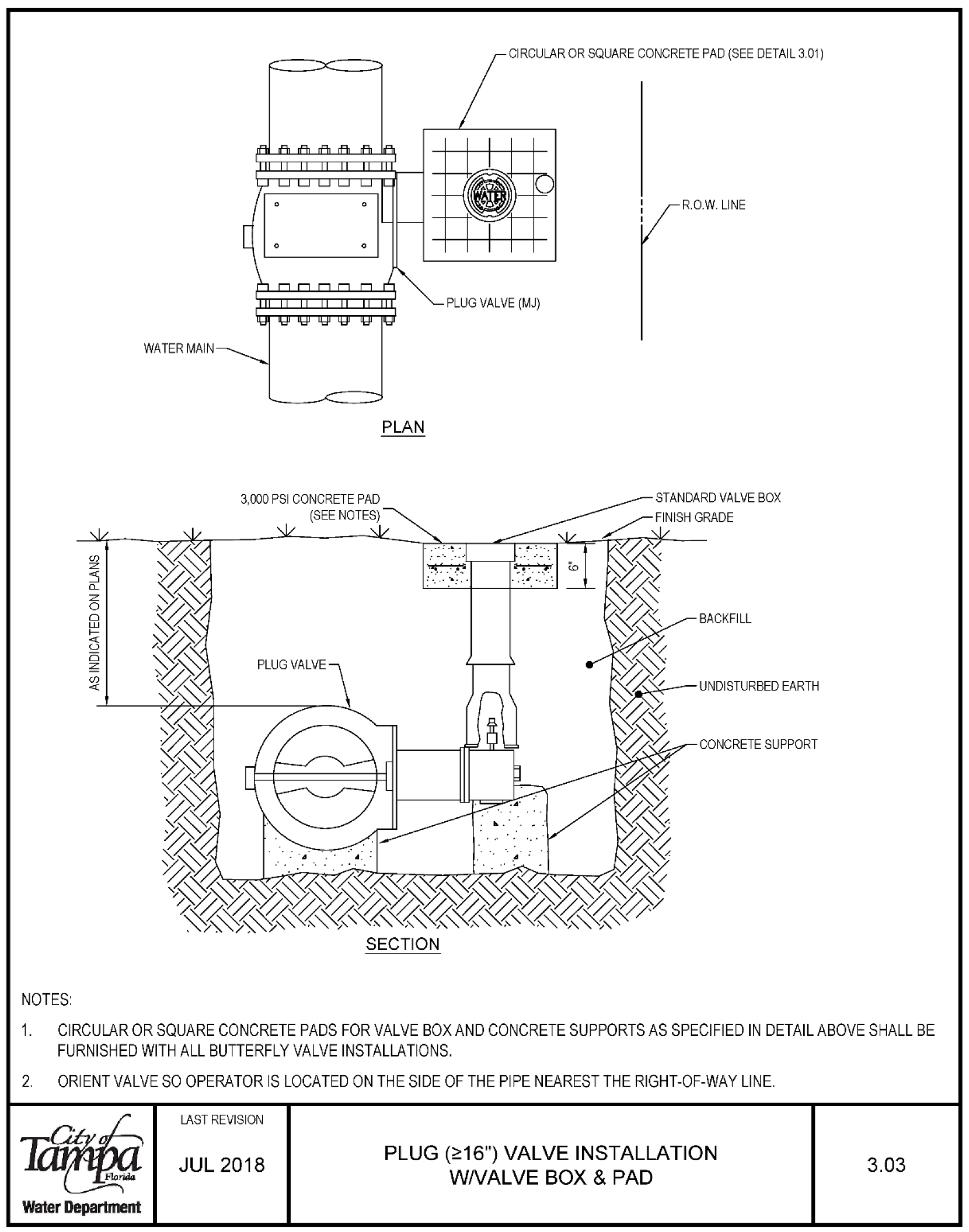
- CIRCULAR OR SQUARE CONCRETE PAD (SEE DETAIL 3.01)
- WATER MAIN
- STANDARD VALVE BOX
- BACKFILL
- UNDISTURBED EARTH
- Circular or square concrete pads for valve box and concrete supports as specified in detail above shall be furnished with all butterfly valve installations.
- Orient valve so operator is located on the side of the pipe nearest the right-of-way line.
Water Department
Last Revision Jul 2018
PLUG (216") VALVE INSTALLATION W/VALVE BOX & PAD 3.03
Valve Box, Slip Type 3.04
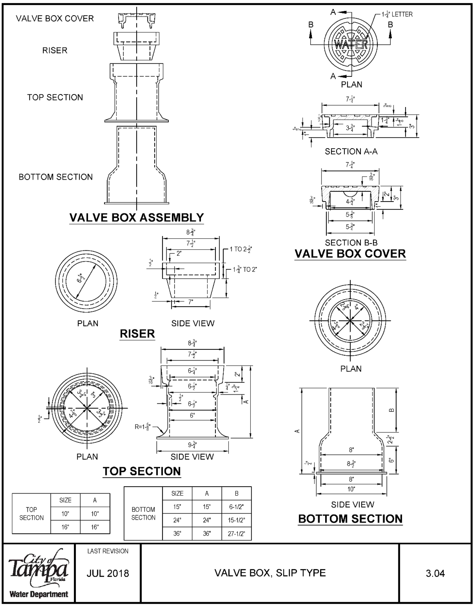
VALVE BOX COVER RISER TOP SECTION BOTTOM SECTION 2 !µ Iv I � --� I I I I I ---1i � � I I I I I I I I I I I I VALVE BOX ASSEMBLY SIZE TOP 10" SECTION 16" PLAN PLAN A 10" 16" t--c2 �. 7_..\•_ __,1 Ir TO 2 t· ill4z i 1� \i /l -i-r□ SIDE VIEW RISER 7--9i � SIDE VIEW TOP SECTION BOTTOM SECTION SIZE 15° 24" 36" A 15" 6-1/2 24 15-1/2 36 27-1/2° LAST REVISION B 1-+' LETTER B TE95 SECTION A-A Eu hL/* is� 71° SECTION B-B VALVE BOX COVER PLAN I 1 � � 8 I-l -jlj 84 I 8 I 10 SIDE VIEW BOTTOM SECTION JUL 2018 VALVE BOX, SLIP TYPE Water Department 3.04
Valve Box (V. Box) Adjustments for Grade Change 3.05
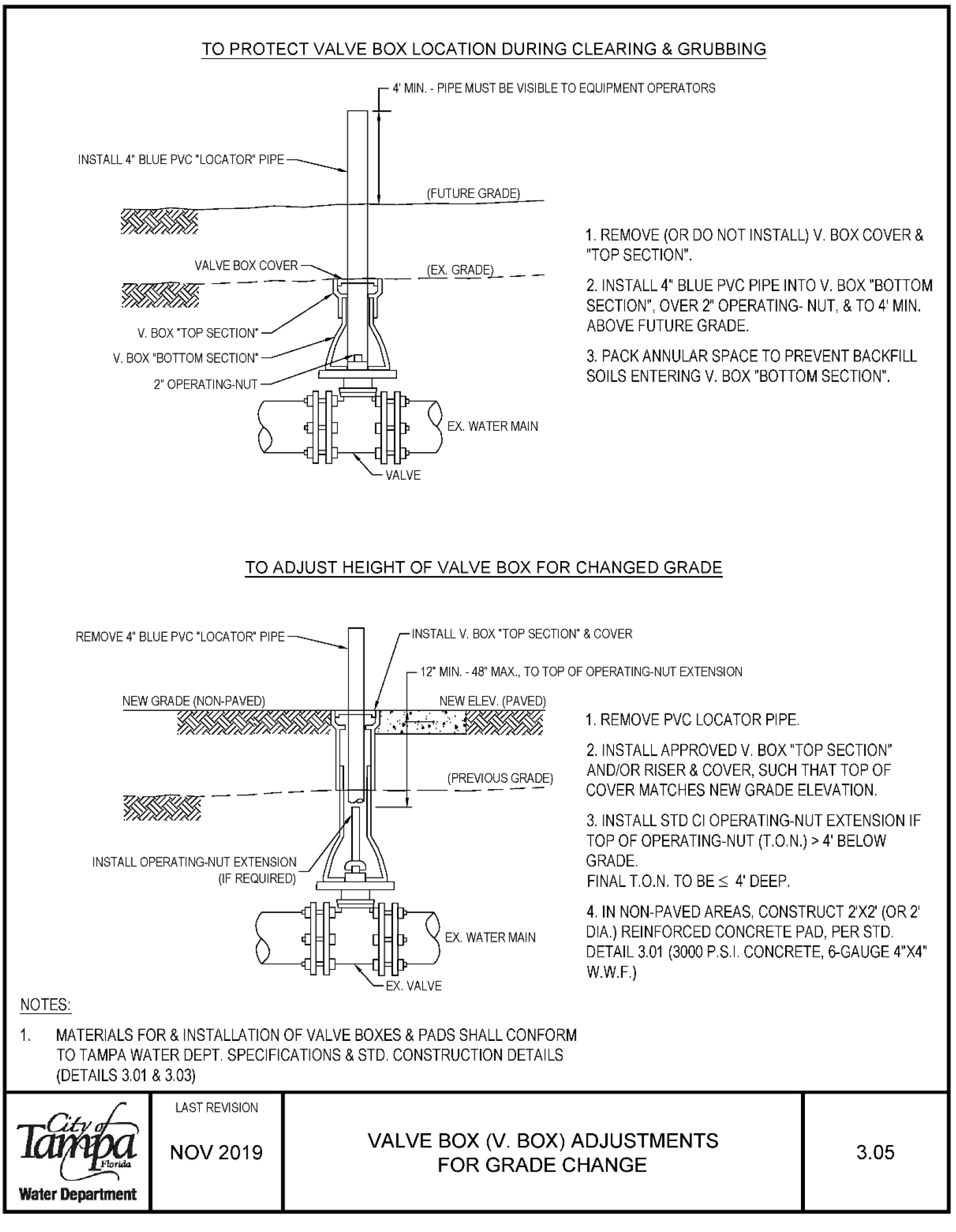
Notes
- TO PROTECT VALVE BOX LOCATION DURING CLEARING & GRUBBING INSTALL 4 BLUE PVC "LOCATOR" PIPE
- V BOX 'TOP SECTION'
- V BOX 'BOTTOM SECTION'
- 2 OPERATl NG-NUT
- 4 MIN PIPE MUST BE VISIBLE TO EQUIPMENT OPERATORS (FUTURE GRADE)
- EX WATER MAIN
- REMOVE (OR DO NOT INSTALL) V. BOX COVER & "TOP SECTION".
- INSTALL 4" BLUE PVC PIPE INTO V. BOX "BOTTOM SECTION", OVER 2 OPERATING-NUT, & TO 4' MIN. ABOVE FUTURE GRADE.
- PACK ANNULAR SPACE TO PREVENT BACKFILL SOILS ENTERING V. BOX "BOTTOM SECTION'.
To Adjust Height of Valve Box for Changed Grade
- REMOVE 4" BLUE PVC 'LOCATOR' PIPE
- INSTALL OPERATING-NUT EXTENSION
- INSTALL V. BOX 'TOP SECTION" & COVER 12° MIN. -48" MAX., TO TOP OF OPERATING-NUT EXTENSION
- REMOVE PVC LOCATOR PIPE
- INSTALL APPROVED V. BOX "TOP SECTION" AND/OR RISER & COVER, SUCH THAT TOP OF COVER MATCHES NEW GRADE ELEVATION.
- INSTALL STD Cl OPERATING-NUT EXTENSION IF TOP OF OPERATING-NUT (T.O.N.) > 4 BELOW GRADE. FINAL T.O.N. TO BE Ł 4 DEEP,
- IN NON-PAVED AREAS, CONSTRUCT 2'X2' (OR 2' DIA.) REINFORCED CONCRETE PAD, PER STD DETAIL 3.01 (3000 PS I CONCRETE, 6-GAUGE 4"X4" W.W.F.)
- MATERIALS FOR & INSTALLATION OF VALVE BOXES & PADS SHALL CONFORM TO TAMPA WATER DEPT. SPECIFICATIONS & STD. CONSTRUCTION DETAILS (DETAILS 3.01 & 3.03)
Water Department
LAST REVISION NOV2019
VALVE BOX (V. BOX) ADJUSTMENTS FOR GRADE CHANGE 3.05
Fire Hydrant Installation 4.01
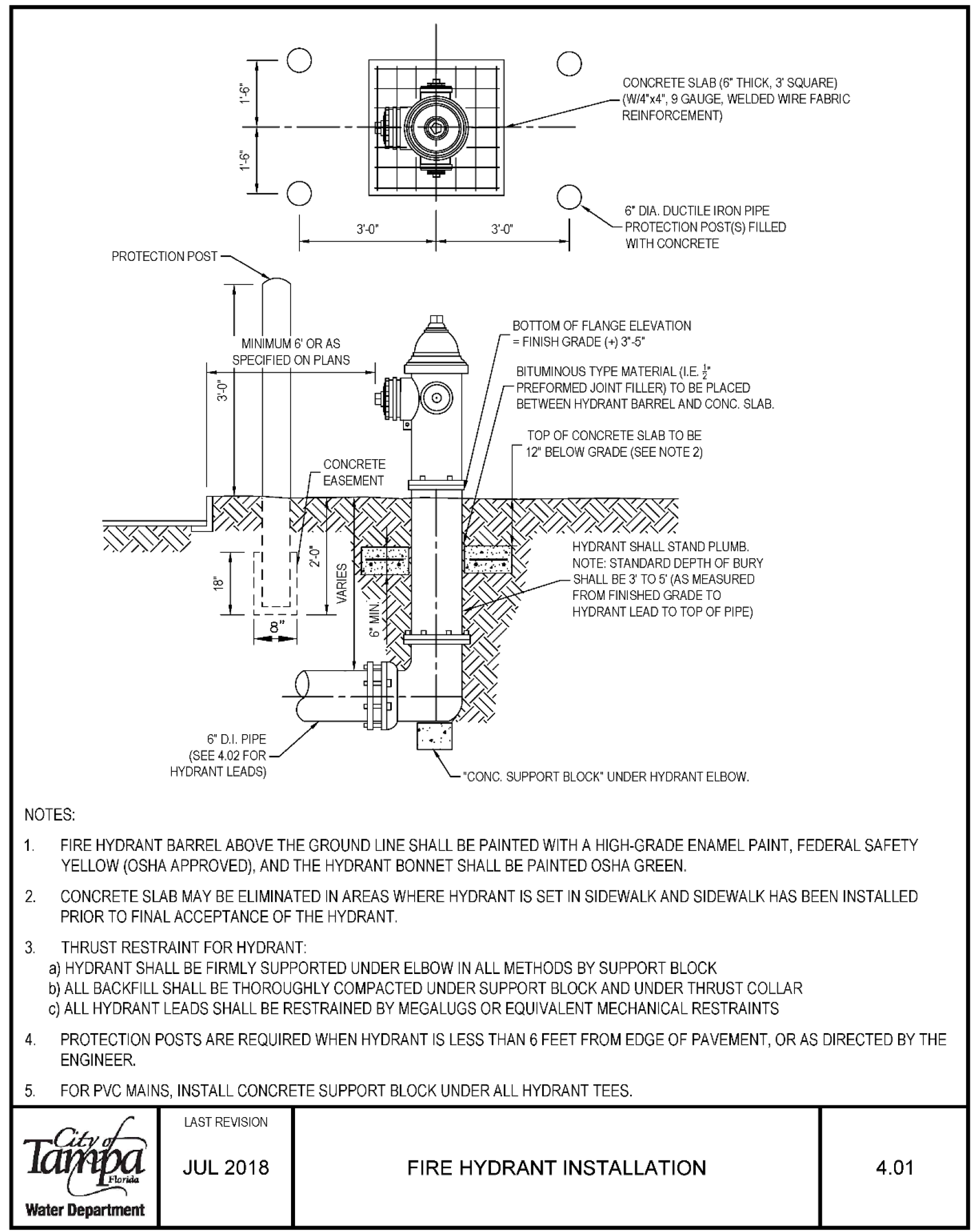
NOTES:
- CONCRETE SLAB (6" THICK, 3 SQUARE) (W/4"x4", 9 GAUGE, WELDED WIRE FABRIC REINFORCEMENT)
- DUTILE IRON PIPE
- PROTECTION POST(S) FILLED WITH CONCRETE
- BOTTOM OF FLANGE ELEVATION MINIMUM 6' OR AS SPECIFIED ON PLANS = FINISH GRADE (+)
- 3"-5" BITUMINOUS TYPE MATERIAL (I.E. ' PREFORMED JOINT FILLER) TO BE PLACED BETWEEN HYDRANT BARREL AND CONC. SLAB.
- 6" D.I. PIPE (SEE 4.02 FOR HYDRANT LEADS)
- TOP OF CONCRETE SLAB TO BE 12" BELOW GRADE (SEE NOTE 2)
- HYDRANT SHALL STAND PLUMB. NOTE: STANDARD DEPTH OF BURY SHALL BE 3 TO 5 (AS MEASURED FROM FINISHED GRADE TO HYDRANT LEAD TO TOP OF PIPE)
- "CONC. SUPPORT BLOCK" UNDER HYDRANT ELBOW.
- FIRE HYDRANT BARREL ABOVE THE GROUND LINE SHALL BE PAINTED WITH A HIGH-GRADE ENAMEL PAINT, FEDERAL SAFETY YELLOW (OSHA APPROVED), AND THE HYDRANT BONNET SHALL BE PAINTED OSHA GREEN.
- CONCRETE SLAB MAY BE ELIMINATED IN AREAS WHERE HYDRANT IS SET IN SIDEWALK AND SIDEWALK HAS BEEN INSTALLED PRIOR TO FINAL ACCEPTANCE OF THE HYDRANT:
- THRUST RESTRAINT FOR HYDRANT:
- HYDRANT SHALL BE FIRMLY SUPPORTED UNDER ELBOW IN ALL METHODS BY SUPPORT BLOCK
- ALL BACKFILL SHALL BE THOROUGHLY COMPACTED UNDER SUPPORT BLOCK AND UNDER THRUST COLLAR
- ALL HYDRANT LEADS SHALL BE RESTRAINED BY MEGALUGS OR EQUIVALENT MECHANICAL RESTRAINTS
- PROTECTION POSTS ARE REQUIRED WHEN HYDRANT IS LESS THAN 6 FEET FROM EDGE OF PAVEMENT, OR AS DIRECTED BY THE ENGINEER.
- FOR PVC MAINS, INSTALL CONCRETE SUPPORT BLOCK UNDER ALL HYDRANT TEES.
LAST REVISION JUL 2018
FIRE HYDRANT INSTALLATION
Water Department 4.01
Fire Hydrant Methods of Installation 4.02
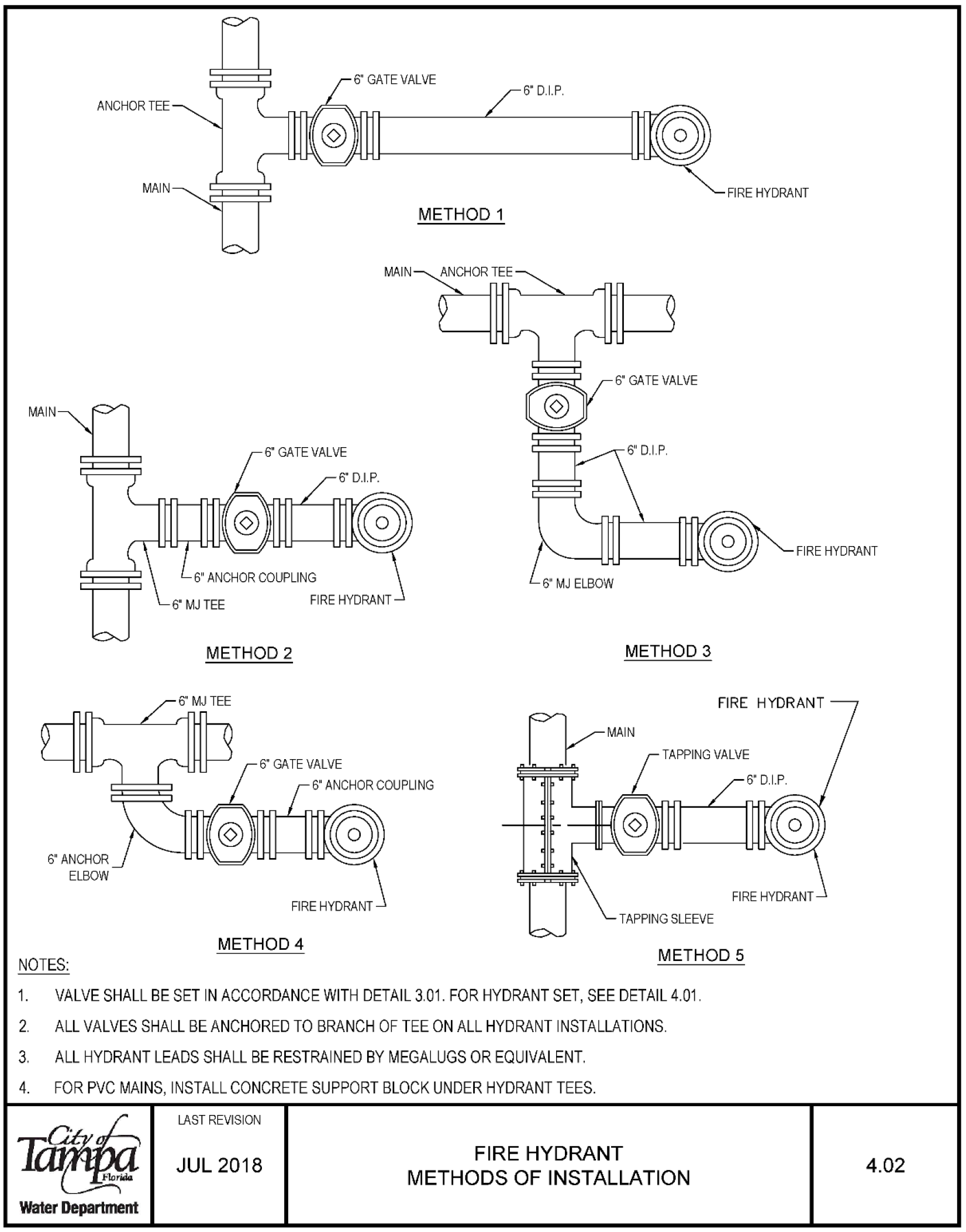
- VALVE SHALL BE SET IN ACCORDANCE WITH DETAIL 3.01. FOR HYDRANT SET, SEE DETAIL 4.01.
- ALL VALVES SHALL BE ANCHORED TO BRANCH OF TEE ON ALL HYDRANT INSTALLATIONS.
- ALL HYDRANT LEADS SHALL BE RESTRAINED BY MEGALUGS OR EQUIVALENT.
- FOR PVC MAINS, INSTALL CONCRETE SUPPORT BLOCK UNDER HYDRANT TEES.
Water Department
LAST REVISION JUL 2018
FIRE HYDRANT METHODS OF INSTALLATION 4.02
Tapping Detail for 3/4", 1", 1-1/2" & 2" w/ DI, Cl, or PVC Pipe 5.01A

| Pipe Size | Corp. Tap Size | Saddle Tap Detail |
|---|---|---|
| DI/CI 12 | DT | DT |
| DI/CI 8 | DT | ss |
| DI/CI 6 | DT | ss |
| DI/CI 4" | ss | ss |
| DI/CI 2, 2-1/2" | ss | NA |
| PVC 8", C-900 | ss | ss |
| PVC 6", C-900 | ss | ss |
| PVC 2"-SDR21 | ss | NA |
| PVC 12 | ss | ss |
| PVC 10 | ss | ss |
| PVC 8 | ss | ss |
| Other* | 6° ss | ss |
| Asbestos Cement, Steel, Galvanized Iron Pipe 3 | ss | NA |
| Non Std PVC, etc 2, 2-1/2" | ss | NA |
- Legend: OT = Direct tap can be allowed; SS = Service saddle is required; NA = Not allowed
- Last revision: Jun 2020
TAPPING DETAIL FOR 3/4", 1", 1-1/2" & 2" W/DI, Cl, OR PVC PIPE Water Department 5.01A
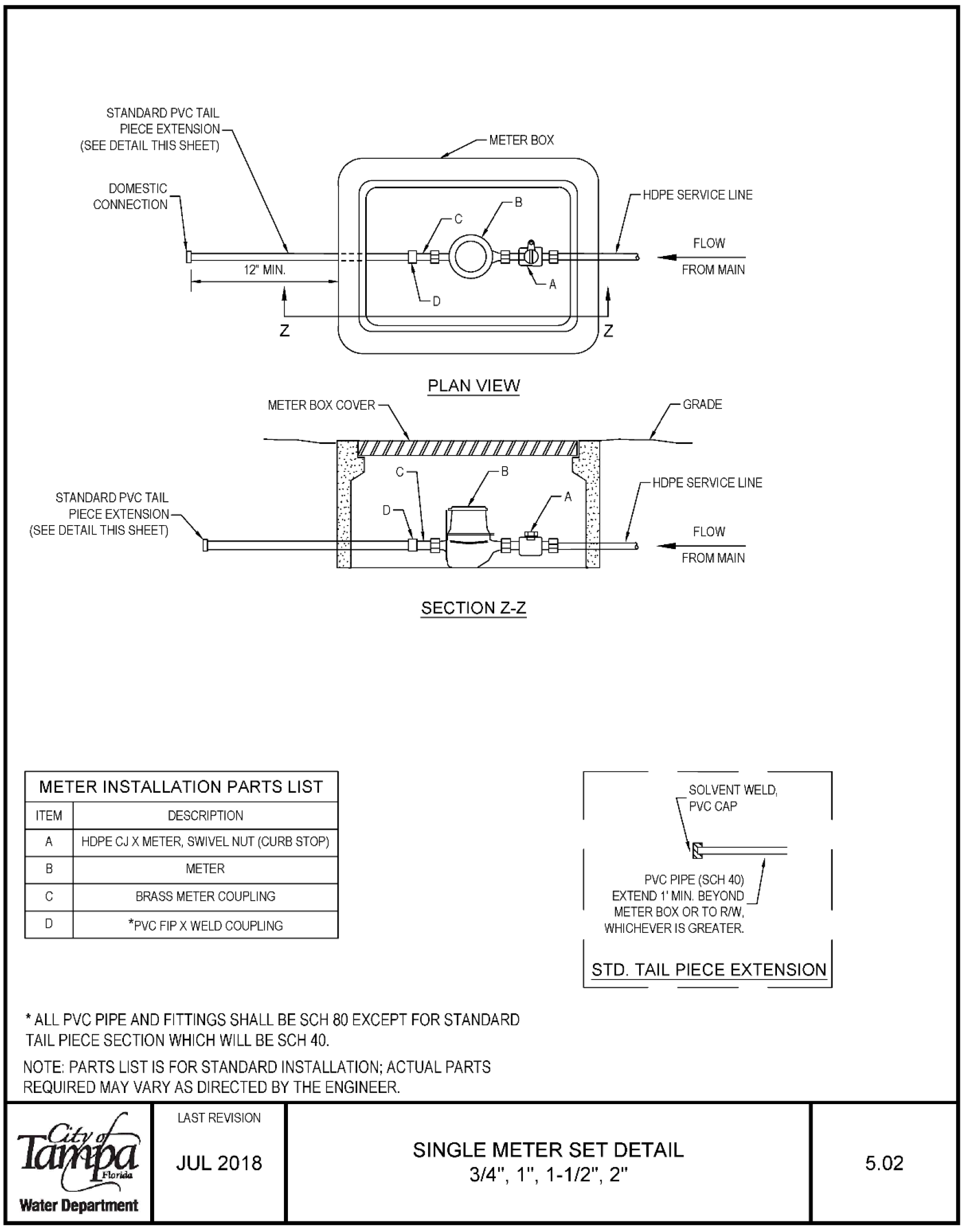
| Item | Description |
|---|---|
| A | HOPE CJ X METER, SWIVEL NUT (CURB STOP) |
| B | METER |
| C | BRASS METER COUPLING |
| D | *PVC FIP X WELD COUPLING |
- All PVC pipe and fittings shall be SCH 80 except for standard tail piece section which will be SCH 40.
- Parts list is for standard installation; actual parts required may vary as directed by the engineer.
Last revision: Jul 2018
Single Meter Set Detail 3/4", 1", 1-1/2", 2"
Water Department 5.02
Dual Meter Set Detail 3/4" & 1" 5.03
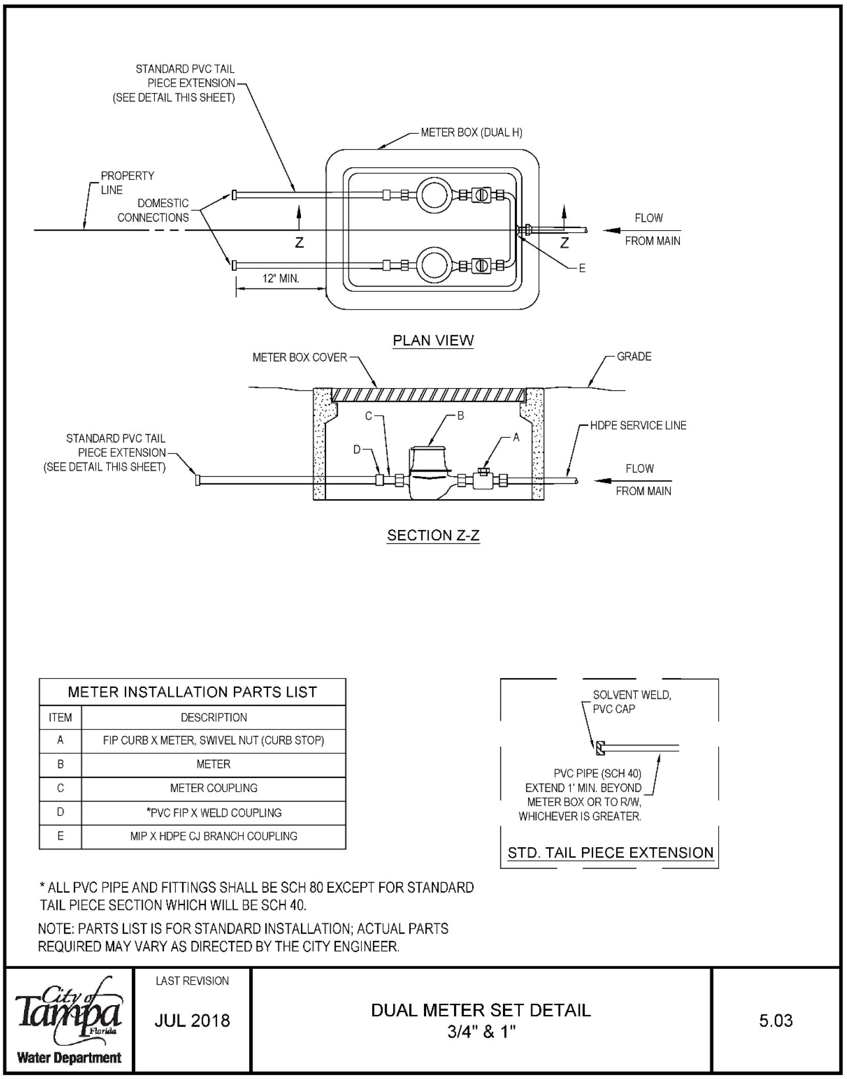
Meter Installation Parts List
| Item | Description |
|---|---|
| A | FIP CURB X METER, SWIVEL NUT (CURB STOP) |
| B | METER |
| C | METER COUPLING |
| D | 'PVC FIP X WELD COUPLING |
| E | MIPX HDPE |
| CJ | BRANCH COUPLING |
* All PVC pipe and fittings shall be SCH 80 except for standard tail piece section which will be SCH 40.
Note: Parts list is for standard installation; actual parts required may vary as directed by the City Engineer.
Last revision: Jul 2018
Water Department
Single & Dual Metered Service - Short Side 3/4", 1", 1-1/2" & 2" 5.04A
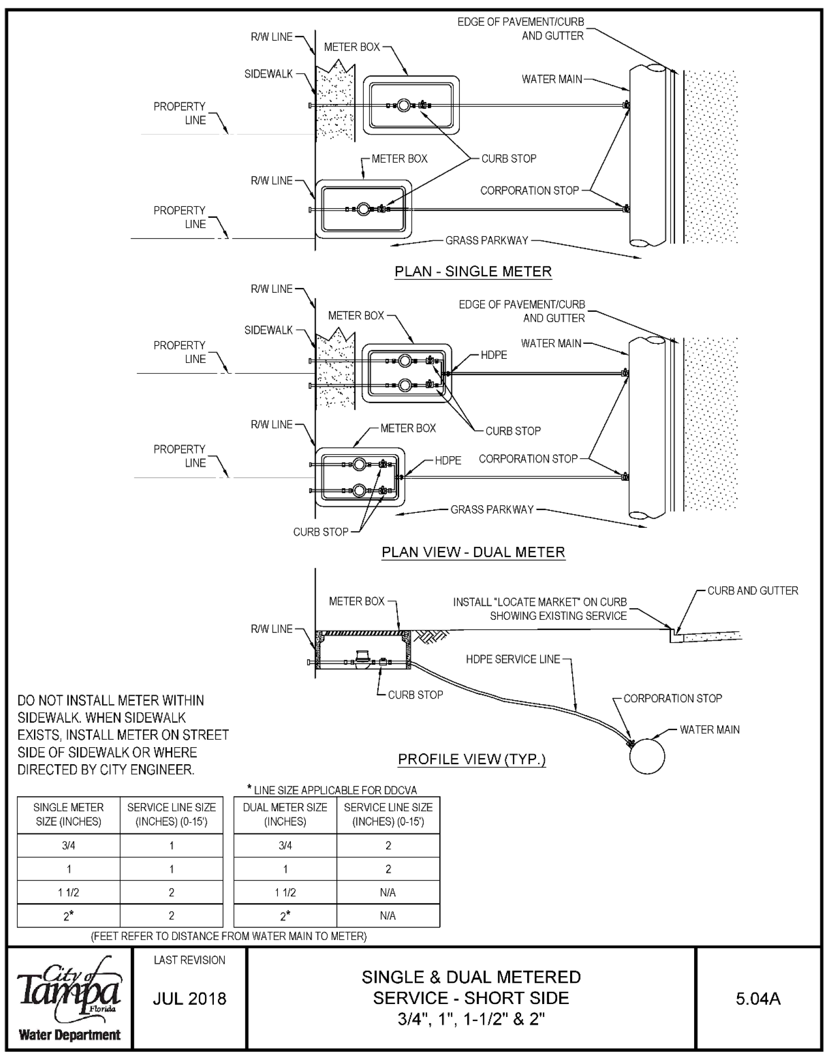
DO NOT INSTALL METER WITHIN SIDEWALK. WHEN SIDEWALK EXISTS, INSTALL METER ON STREET SIDE OF SIDEWALK OR WHERE DIRECTED BY CITY ENGINEER.
| Service Type | Meter Size (inches) | Service Line Size (inches) | Distance (feet) |
|---|---|---|---|
| Single Meter | 3/4 | 1 | 0-15 |
| Single Meter | 1 | 1 | 0-15 |
| Single Meter | 1-1/2 | 2 | 0-15 |
| Single Meter | 2 | 2 | 0-15 |
| Dual Meter | 3/4 | 2 | 0-15 |
| Dual Meter | 1 | 2 | 0-15 |
| Dual Meter | 1-1/2 | N/A | 0-15 |
| Dual Meter | 2 | N/A | 0-15 |
(FEET REFER TO DISTANCE FROM WATER MAIN TO METER)
Water Department
LAST REVISION JUL 2018
Single & Dual Metered Service - Long Side 3/4", 1", 1-1/2" & 2" 5.05A
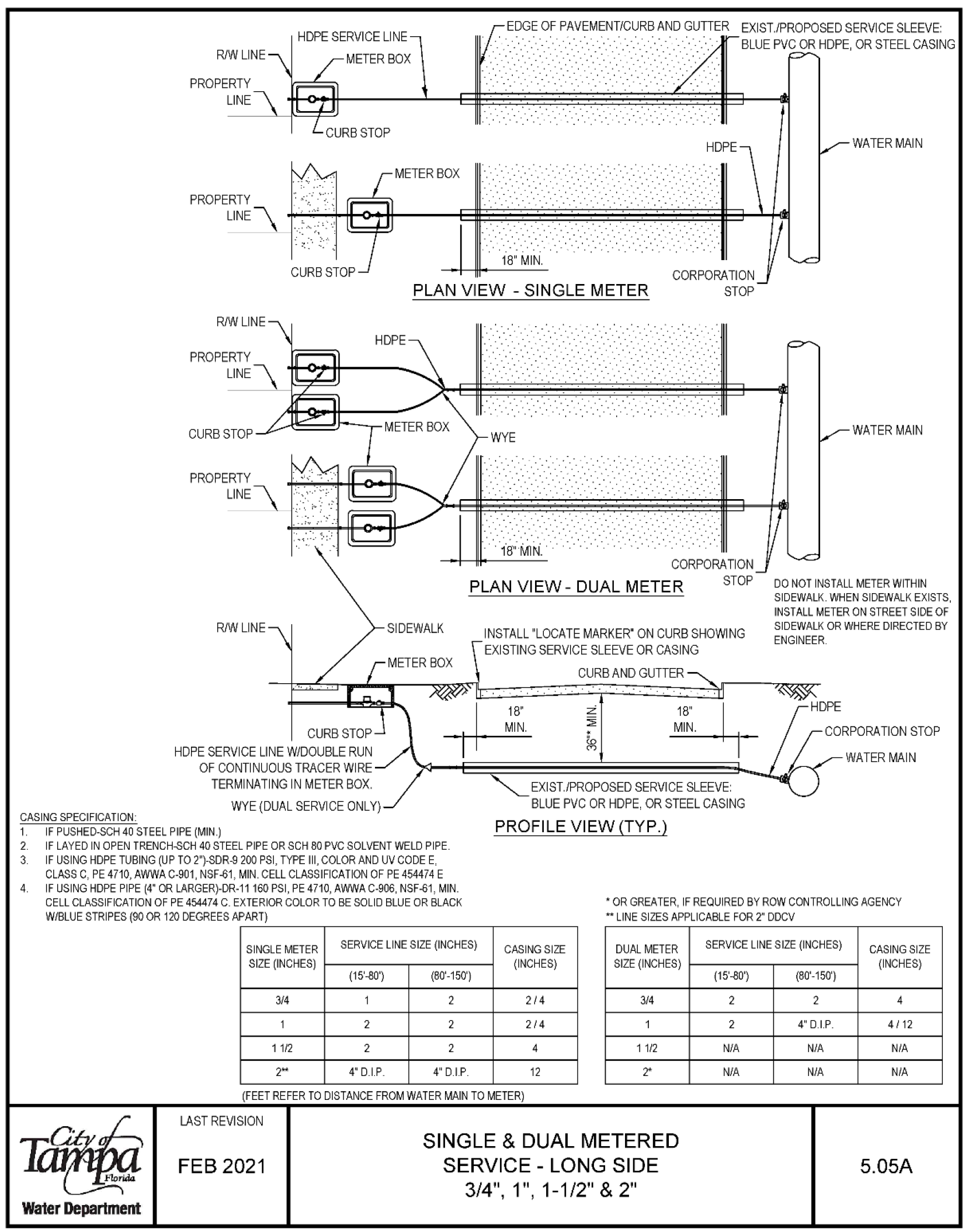
EXIST./PROPOSED SERVICE SLEEVE: R/W LINE HOPE SERVICE LINE METER BOX BLUE PVC OR HOPE, OR STEEL CASING PROPERTY uNE PLAN VIEW -SINGLE METER CASING SPECIFICATION: RAW LINE CURB STOP R/WLINE CURB STOP HDPE SERVICE LINE W/DOUBLE RUN OF CONTINUOUS TRACER WIRE TERMINATING IN METER BOX. WYE (DUAL SERVICE ONLY) 1 IF PUSHED-SCH 40 STEEL PIPE (MIN.) 2. IF LAYE□ IN OPEN TRENCH-SCH 40 STEEL PIPE OR SCH BO PVC SOLVENT WELD PIPE. 3. IF USING HDPE TUBING (UP TO 2")-SDR-9 200 PSI, TYPE III, COLOR AND UV CODE E CLASS C, PE 4710, AWWA C-901, NSF-61, MIN. CELL CLASSIFICATION OF PE 454474 E 4. IF USING HDPE PIPE (4" OR LARGER)-DR-11 160 PSI, PE 4710, AWWA C-906, NSF-61, MIN. INSTALL 'LOCATE MARKER" ON CURB SHOWING EXISTING SERVICE SLEEVE OR CASING CURB AND GUTTER EXIST/PROPOSED SERVICE SLEEVE: BLUE PVC OR HOPE, OR STEEL CASING PROFILE VIEW (TYP.) WATER MAIN WATER MAIN DO NOT INSTALL METER WITHIN SIDEWALK. WHEN SIDEWALK EXISTS, INSTALL METER ON STREET SIDE OF SIDEWALK OR WHERE DIRECTED BY ENGINEER · rCORPORATION STOP / WATER MAIN CELL CLASSIFICATION OF PE 454474 C. EXTERIOR COLOR TO BE SOLID BLUE OR BLACK WIBLUE STRIPES (90 OR 120 DEGREES APART) * OR GREATER, IF REQUIRED BY ROW CONTROLLING AGENCY ** LINE SIZES APPLICABLE FOR 2 DDCV Water Department SINGLE METER SERVICE LINE SIZE (INCHES) CASING SIZE DUAL METER SIZE (INCHES) (INCHES) SIZE (INCHES) (15'-80°) (80'-150) 3/4 1 2 2/4 3/4 1 2 2 2/4 1 1 1/2 2 2 4 1 1/2 2 4' D.I.P 4" D.I.P 12 2 (FEET REFER TO DISTANCE FROM WATER MAIN TO METER) LAST REVISION FEB 2021 SINGLE & DUAL METERED SERVICE -LONG SIDE 3/4", 1", 1-1/2" & 2" SERVICE LINE SIZE (INCHES) (15'-80) (80'-150') 2 2 2 4" D.I.P N/A N/A N/A N/A CASING SIZE (INCHES) 4 4 / 12 NIA N/A 5.05A
3/4" or 1" Single Service HDPE Meter Box 5.10
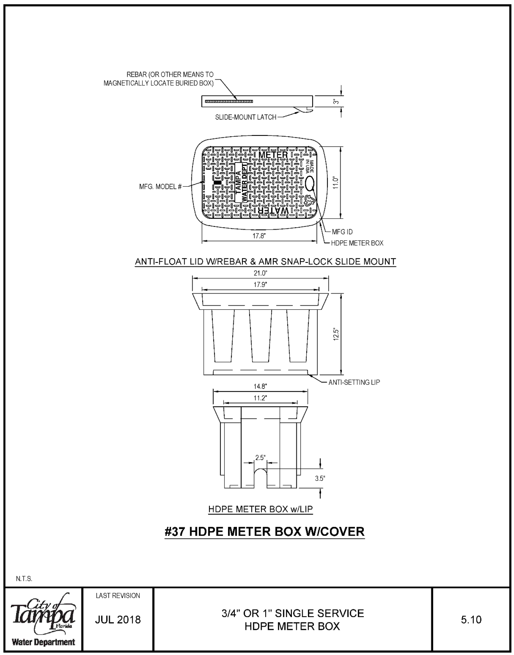
N.T.S. Water Department REBAR (OR OTHER MEANS TO MAGNETICALLYLOCATEBURIEDBOX)2 __j □ � □ SLIDE-MOUNT LATCH 1 MFG. MODEL# ANTI-FLOAT LID W/REBAR & AMR SNAP-LOCK SLIDE MOUNT 21.0" LAST REVISION JUL 2018 17.9° 2 5 HDPE METER BOX w/LIP #37 HDPE METER BOX W/COVER 3/4" OR 1" SINGLE SERVICE HOPE METER BOX 5.10
3/4" or 1" Dual Service HDPE Meter Box 5.11
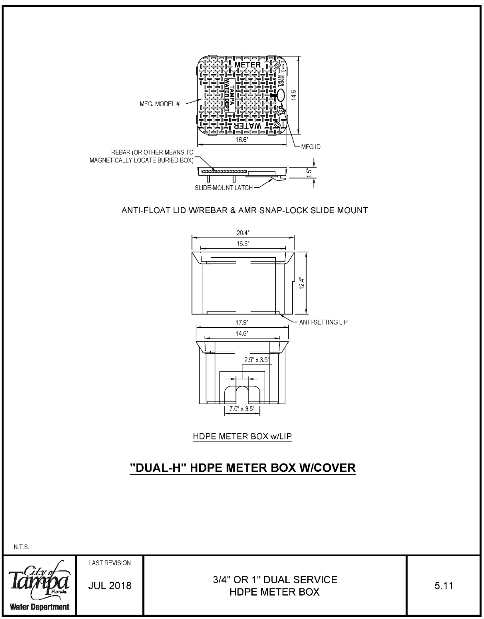
N.T.S. Water Department MFG. MODEL # MFGID REBAR (OR OTHER MEANS TO MAGNETICALLY LOCATE BURIED BOX)� _j_ 3□-suoewoum.-I ANTI-FLOAT LID W/REBAR & AMR SNAP-LOCK SLIDE MOUNT 20.4° 16.6' I 17.9 ANTI SETTING LIP HOPE METER BOX w/LIP "DUAL-H" HDPE METER BOX W/COVER LAST REVISION JUL 2018 3/4" OR 1 DUAL SERVICE HOPE METER BOX 5.11
1-1/2" & 2" Single Service HDPE Meter Box 5.12
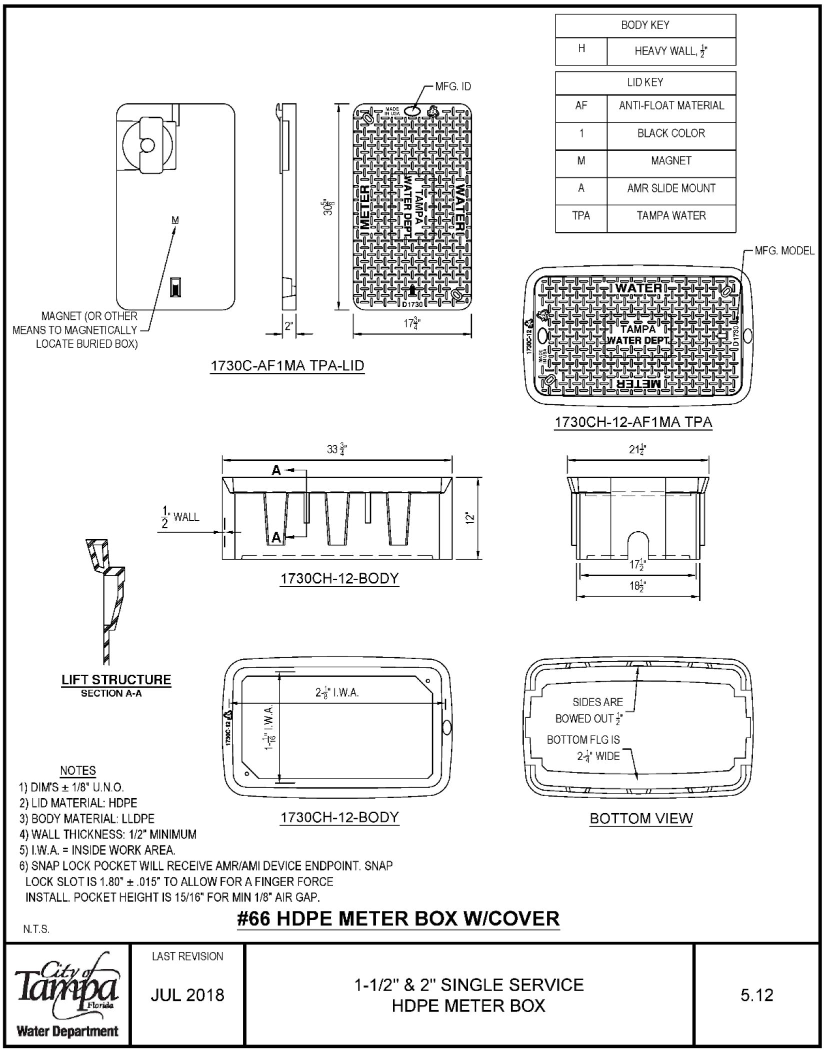
- MAGNET (OR OTHER MEANS TO MAGNETICALLY LOCATE BURIED BOX)
- LIFT STRUCTURE
- SECTION A-A
- NOTES
- 1) DIM'S ± 1/8" U.N.O.
- 2) LID MATERIAL: HDPE 1730C-AF1MA TPA-LID 1730CH-12-BODY 2I.W.A.
- 3) BODY MATERIAL LLDPE 1730CH-12-BODY
- 4) WALL THICKNESS: 1/2 MINIMUM
- 5) I.W.A. = INSIDE WORK AREA.
- 6) SNAP LOCK POCKET WILL RECEIVE AMR/AMI DEVICE ENDPOINT. SNAP LOCK SLOT IS 1.80" ± .015" TO ALLOW FOR A FINGER FORCE INSTALL. POCKET HEIGHT IS 15/16" FOR MIN 1/8" AIR GAP.
- BODY KEY H HEAVY WALL, ' LIDKEY AF ANTI-FLOAT MATERIAL BLACK COLOR M MAGNET A AMR SLIDE MOUNT TPA TAMPA WATER 1730CH-12-AF1MA TPA 21-' IT L_ EE□ SIDES ARE BOWED OUT A' BOTTOM FLG IS 2. WIDE
- BOTTOM VIEW N.T.S. #66 HOPE METER BOX W/COVER
- Water Department LAST REVISION JUL 2018
- 1-1/2" & 2" SINGLE SERVICE HOPE METER BOX 5.12
Above Ground Large Meter Assembly (3" or Larger) 6.01A
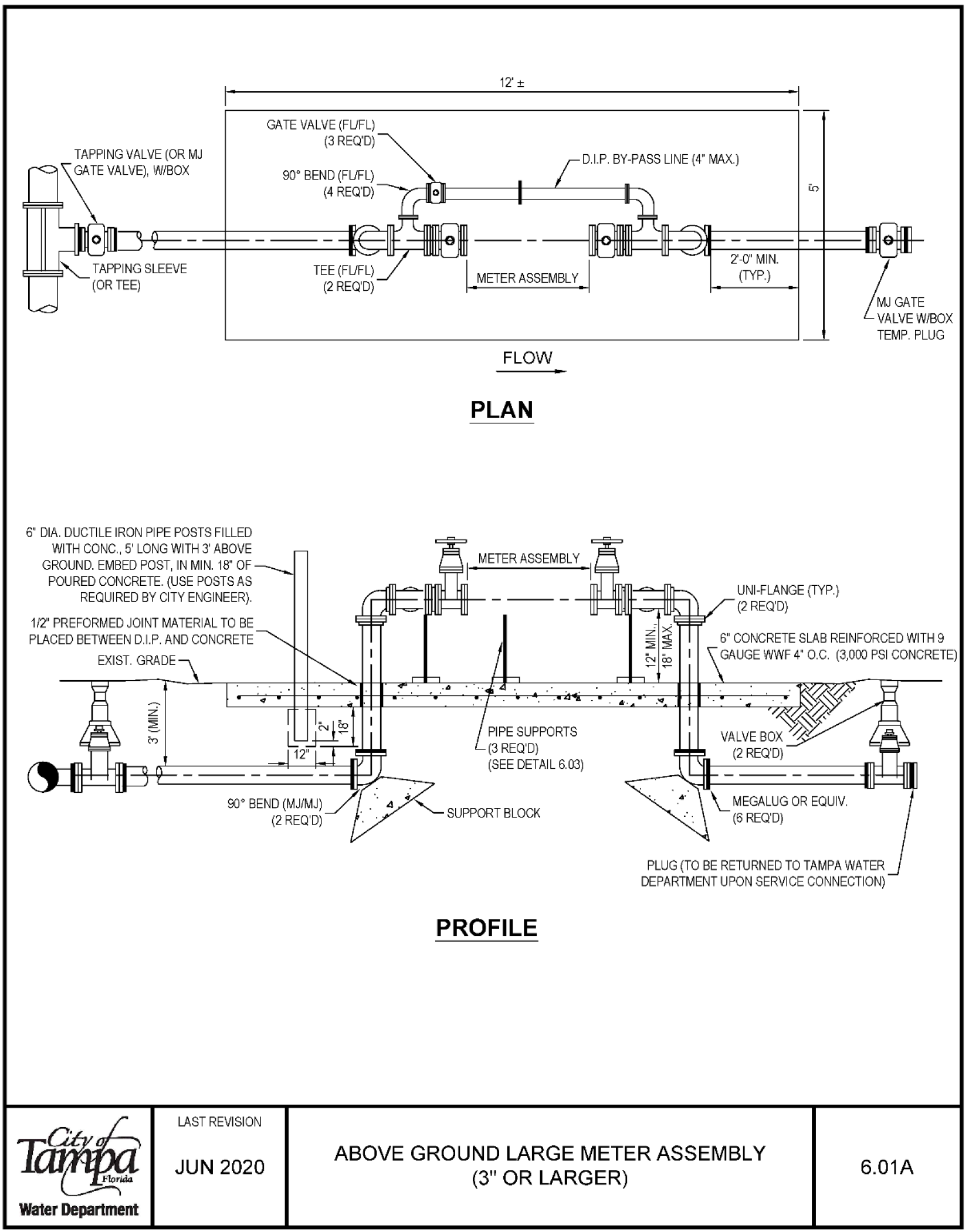
6' DIA. DUCTILE IRON PIPE POSTS FILLED WITH CONC., 5' LONG WITH 3' ABOVE GROUND. EMBED POST, IN MIN. 18" OF POURED CONCRETE. (USE POSTS AS REQUIRED BY CITY ENGINEER). 1/2" PREFORMED JOINT MATERIAL TO BE PLACED BETWEEN D.I.P. AND CONCRETE EXIST GRADE 90° BEND (MJ/MJ) (2 REQ'D) LAST REVISION JUN 2020 Water Department 12± FLOW PLAN SUPPORT BLOCK PROFILE D I P BY PASS LINE (4" MAX) 2'-0" MIN. (TYP.) UNI-FLANGE (TYP.) (2REQ'D) ..-Zeme. TEMP. PLUG 6" CONCRETE SLAB REINFORCED WITH 9 PLUG (TO BE RETURNED TO TAMPA WATER DEPARTMENT UPON SERVICE CONNECTION) ABOVE GROUND LARGE METER ASSEMBLY (3" OR LARGER) 6.01A
Below Ground Large (3" or Larger) Meter Installation 6.01B
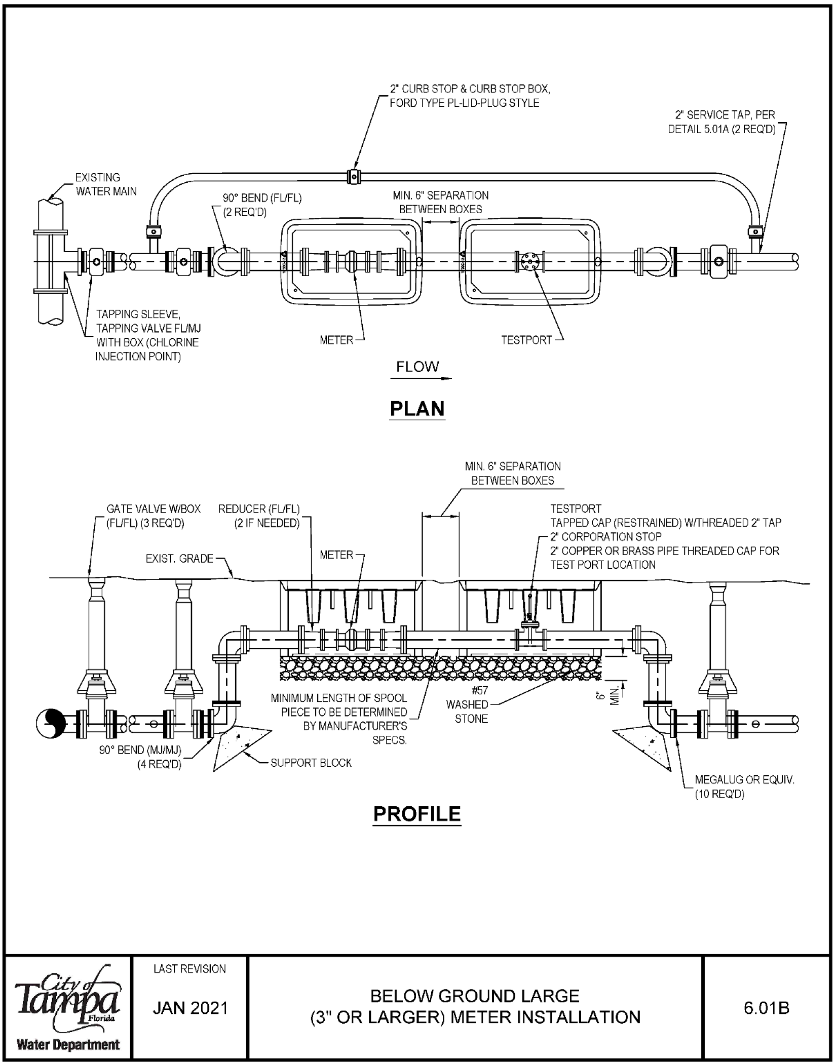
Above Ground Pipe Supports 6.03
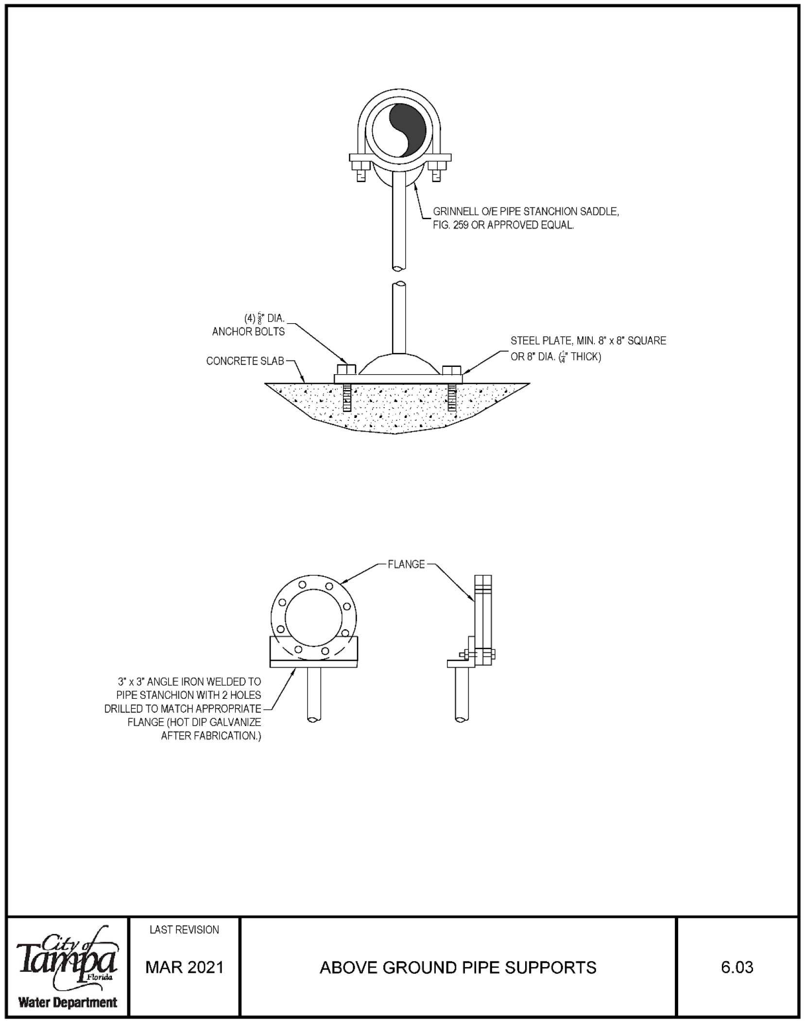
(4)DIA. ANCHOR BOLTS 3 x 3 ANGLE IRON WELDED TO PIPE STANCHION WITH 2 HOLES DRILLED TO MATCH APPROPRIATE FLANGE (HOT DIP GALVANIZE AFTER FABRICATION.) LAST REVISION MAR 2021 Water Department FLANGE GRINNELL 0/E PIPE STANCHION SADDLE, FIG. 259 OR APPROVED EQUAL. STEEL PLATE, MIN. 8 x 8° SQUARE OR 8 DIA. (§" THICK) ABOVE GROUND PIPE SUPPORTS 6.03
Meter In Vault 6.04
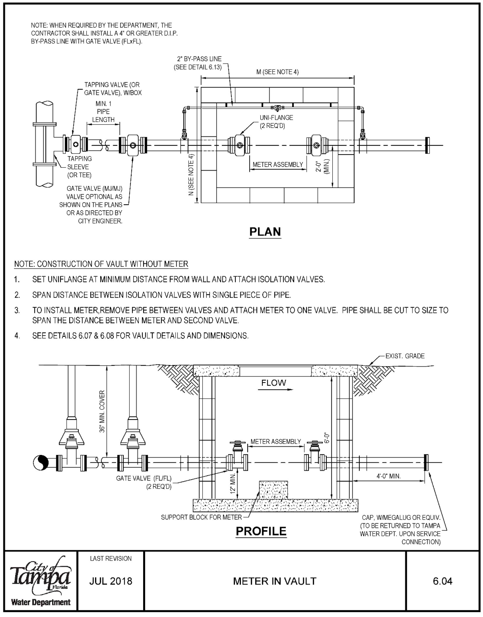
NOTE: WHEN REQUIRED BY THE DEPARTMENT, THE CONTRACTOR SHALL INSTALL A 4" OR GREATER D.I.P. BY-PASS LINE WITH GATE VALVE (FLxFL). 2 BY-PASS LINE (SEE DETAIL 6.13) TAPPING VALVE {OR GATE VALVE), W/BOX GATE VALVE (MJ/MJ) VALVE OPTIONAL AS SHOWN ON THE PLANS OR AS DIRECTED BY CITY ENGINEER. NOTE: CONSTRUCTION OF VAULT WITHOUT METER LL LU o z M (SEE NOTE 4) UNI-FLANGE (2 REQ'D) PLAN 1. SET UNIFLANGE AT MINIMUM DISTANCE FROM WALLAND ATTACH ISOLATION VALVES. 2. SPAN DISTANCE BETWEEN ISOLATION VALVES WITH SINGLE PIECE OF PIPE. 3. TO INSTALL METER,REMOVE PIPE BETWEEN VALVES AND ATTACH METER TO ONE VALVE. PIPE SHALL BE CUT TO SIZE TO SPAN THE DISTANCE BETWEEN METER AND SECOND VALVE. 4. SEE DETAILS 6.07 & 6.08 FOR VAULT DETAILS AND DIMENSIONS. LAST REVISION JUL 2018 METER IN VAULT Water Department EXIST GRADE 6.04
Vault Construction Detail for Meter/DDCVA 6.07
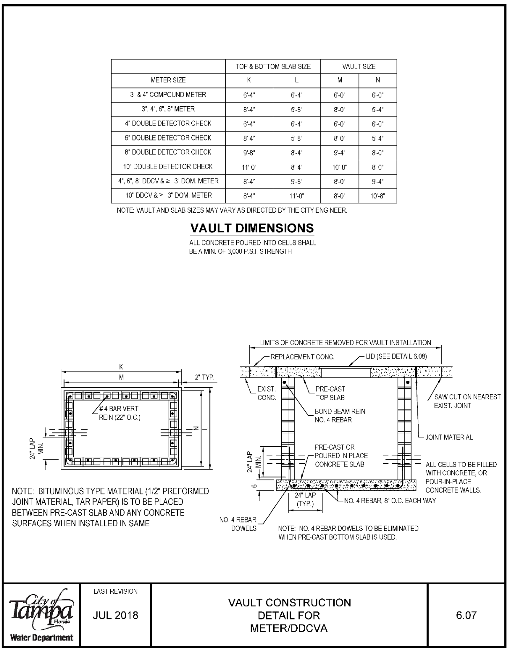
| Vault Type | Top & Bottom Slab Size | Vault Size | Meter Size | K | L | M | N |
|---|---|---|---|---|---|---|---|
| 3 & 4 Compound Meter | 6'-4" | 6'-4" | 6-0 | 6'-0" | 3", 4", 6", 8" | ||
| 4' Double Detector Check | 8'-4" | 5'-8" | 8'-0" | 5'-4" | 4' | ||
| 6 Double Detector Check | 6'-4" | 6'-4" | 6'-0" | 6'-0" | 6 | ||
| 8 Double Detector Check | 8'-4" | 5'-8" | 8'-0" | 5'-4" | 8 | ||
| 9'-8 Double Detector Check | 9'-8" | 8'-4" | 9'-4" | 8'-0" | 10" | ||
| 11'-0" Double Detector Check | 11'-0" | 8'-4" | 10'-8" | 8'-0" | 4", 6", 8" DDCV & 2 3" Dom. Meter | ||
| 10" DDCV & 2 3 Dom. Meter | 8'-4" | 11'-0" | 8'-0" | 10'-8" |
NOTE: Vault and slab sizes may vary as directed by the City Engineer. Vault dimensions: All concrete poured into cells shall be a minimum of 3,000 P.S.I. strength. Limits of concrete removed for vault installation/replacement: see Detail 6.08.
- All cells to be filled with concrete.
- No. 4 rebar dowels pour-in-place in concrete walls, 8" O.C. each way.
- No. 4 rebar dowels to be eliminated when pre-cast bottom slab is used.
- Bituminous type material (1/2" preformed joint material, tar paper) is to be placed between pre-cast slab and any concrete surfaces when installed in same.
Last revision Jul 2018. Water Department.
Vault Concrete Slab Detail for Meter/DDCVA 6.08
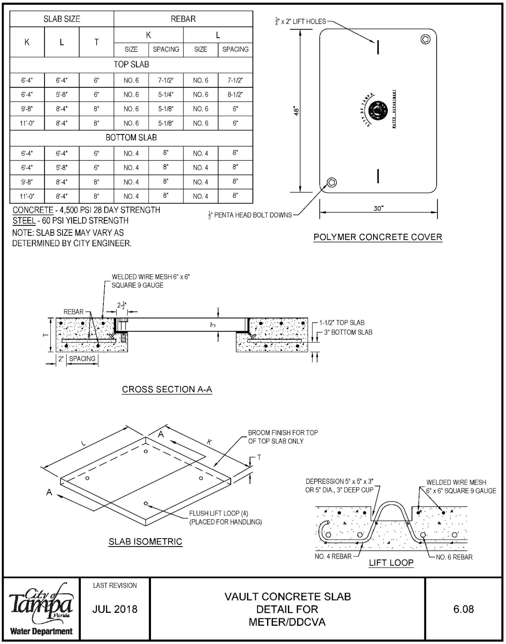
| Slab | Size | Rebar | Spacing |
|---|---|---|---|
| Top Slab | 6'-4" x 6'-4" x 6" | No. 6 | 7-1/2" |
| Top Slab | 6'-4" x 5'-8" x 6" | No. 6 | 5-1/4" |
| Top Slab | 9'-8" x 8'-4" x 8" | No. 6 | 5-1/8" |
| Top Slab | 11'-0" x 8'-4" x 8" | No. 6 | 5-1/8" |
| Bottom Slab | 6'-4" x 6'-4" x 6" | No. 4 | 8" |
| Bottom Slab | 6'-4" x 5'-8" x 6" | No. 4 | 8" |
| Bottom Slab | 9'-8" x 8'-4" x 8" | No. 4 | 8" |
| Bottom Slab | 11'-0" x 8'-4" x 8" | No. 4 | 8" |
- Concrete: 4,500 PSI 28 day strength
- Steel: 60 PSI yield strength
- 4 penta head bolt downs 30"
- Slab size may vary as determined by City Engineer.
- Polymer concrete cover
- Welded wire mesh 6" x 6" square 9 gauge
- Broom finish for top of top slab only
Cross Section A-A. Slab Isometric. Last revision Jul 2018.
Meter w/ Strainers in Above Ground Vault 6.09
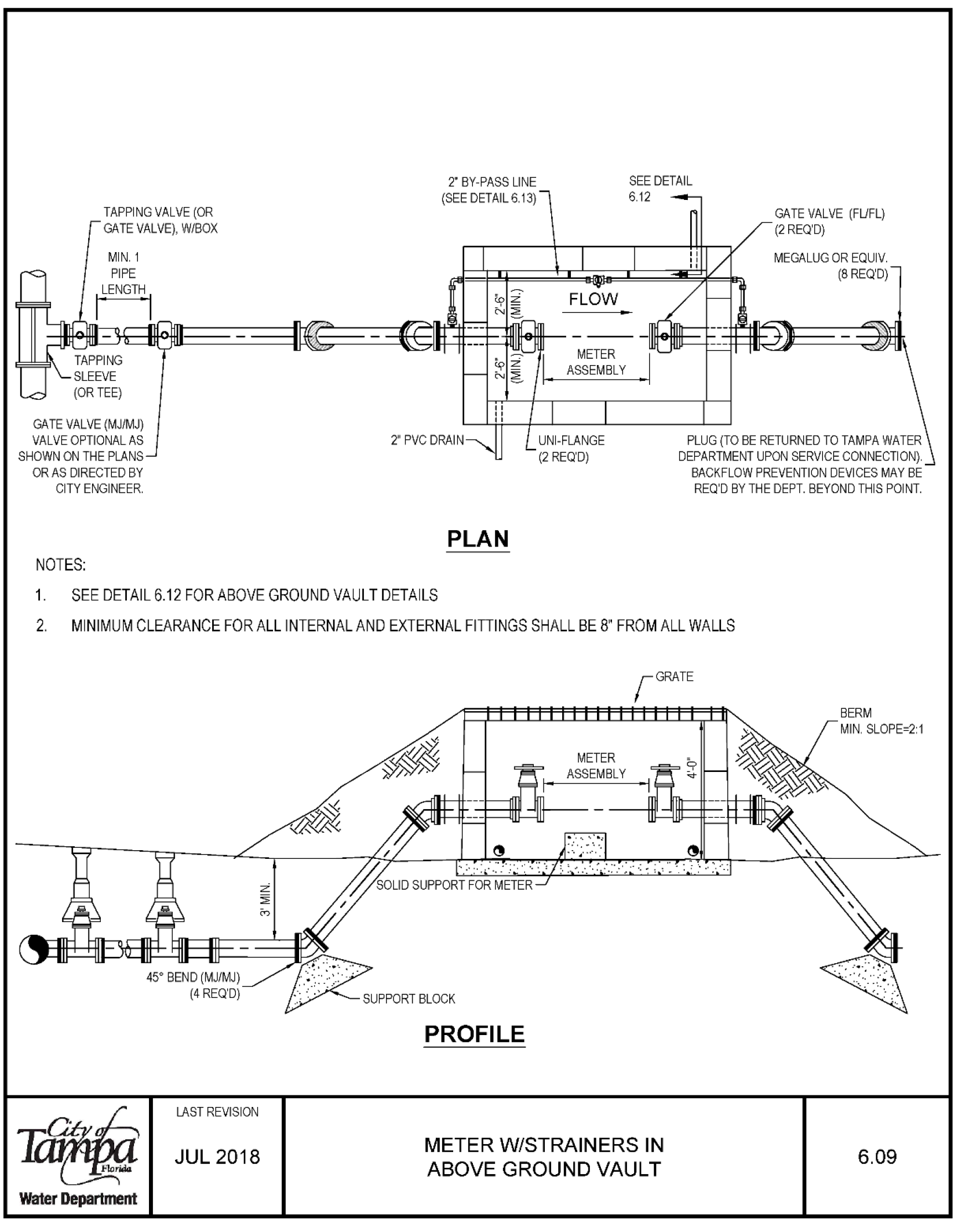
TAPPING VALVE (OR GATE VALVE), W/BOX MIN.1 PIPE 2' BY-PASS LINE (SEE DETAIL 6.13) FLOW SEE DETAIL 6.12 GATE VALVE (FUFL) (2 REQ'D) MEGALUG OR EQUIV. (8 REQ'D) GATE VALVE (MJ/MJ) VALVE OPTIONAL AS SHOWN ON THE PLANS OR AS DIRECTED BY CITY ENGINEER Ł-ME-TER---" i PLUG (TO BE RETURNED TO TAMPA WATER DEPARTMENT UPON SERVICE CONNECTION). BACKFLOW PREVENTION DEVICES MAY BE REQ'D BY THE DEPT. BEYOND THIS POINT.
- PLAN NOTES:
- 1. SEE DETAIL 6.12 FOR ABOVE GROUND VAULT DETAILS
- 2. MINIMUM CLEARANCE FOR ALL INTERNAL AND EXTERNAL FITTINGS SHALL BE 8" FROM ALL WALLS
Water Department LAST REVISION JUL 2018 PROFILE METER W/STRAINERS IN ABOVE GROUND VAULT BERM MIN. SLOPE=2:1 6.09
Above Ground Vault Cross Section 6.12
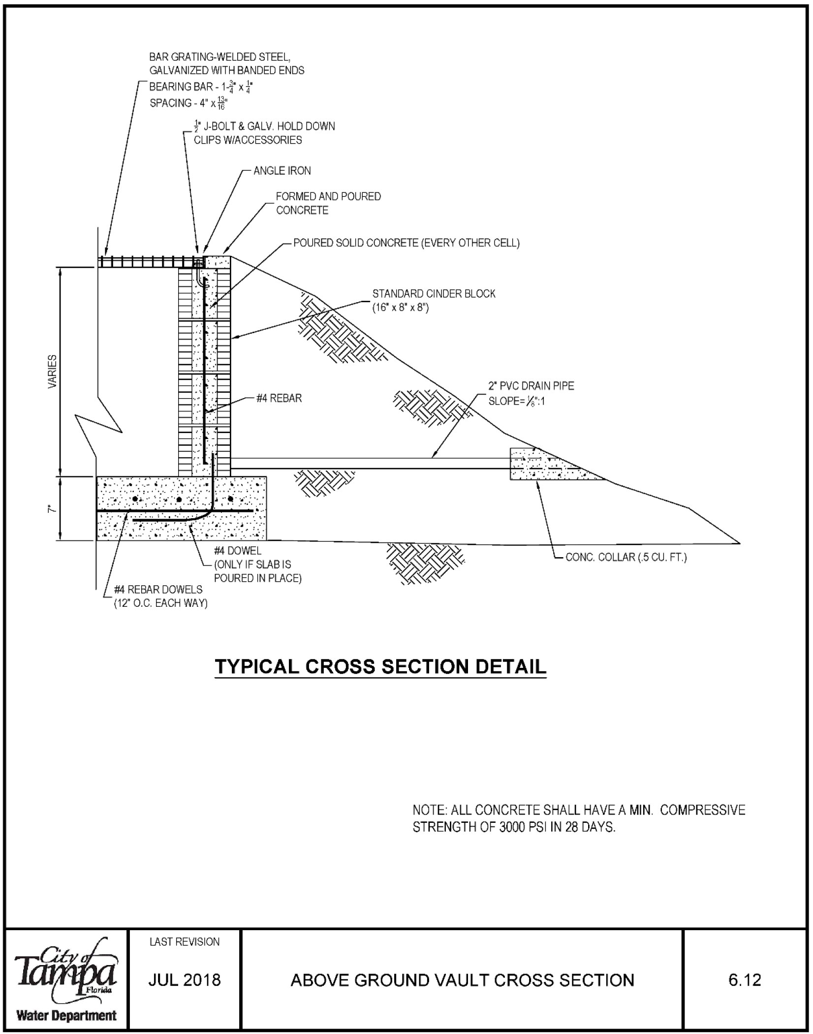
BAR GRATl NG-WELDED STEEL, GALVANIZED WITH BANDED ENDS ! JBOLT & GALV HOLD DOWN CUPS WIACCESSORIES ANGLE IRON FORMED AND POURED CONCRETE POURED SOLID CONCRETE (EVERY OTHER CELL) #4 REBAR DOWELS (12 O.C. EACH WAY) STANDARD CINDER BLOCK (16° x 8" x 8") Ł 2 PVC DRAIN PIPE SLOPE=":1 TYPICAL CROSS SECTION DETAIL NOTE ALL CONCRETE SHALL HAVE A MIN. COMPRESSIVE STRENGTH OF 3000 PSI IN 28 DAYS. LAST REVISION JUL 2018 ABOVE GROUND VAULT CROSS SECTION 6.12 Water Department
2" By-Pass Line 6.13
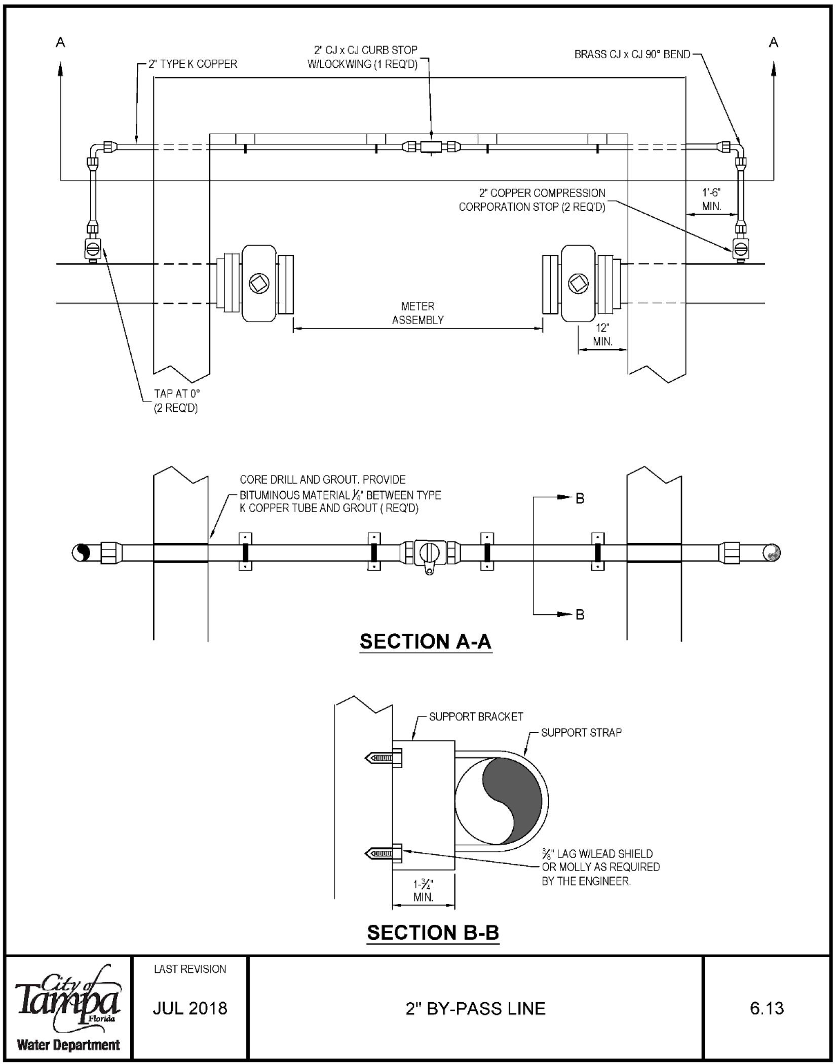
Water Department 2' TYPE K COPPER 2 CJ x CJ CURB STOP W/LOCKWING (1 REQ'D) METER ASSEMBLY CORE DRILL AND GROUT. PROVIDE BRASS CJ x CJ 90° BEND 2 COPPER COMPRESSION CORPORATION STOP (2 REQ'D) /BITUMINOLS MATERIAL)" BETWEEN TYPE K COPPER TUBE AND GROUT ( REQ'D) . . B B SECTION A-A SECTION B-B LAST REVISION JUL 2018 2" BY-PASS LINE A 6.13
1-1/2" & 2" Single Service HDPE Meter Box -Reclaimed 7.02R
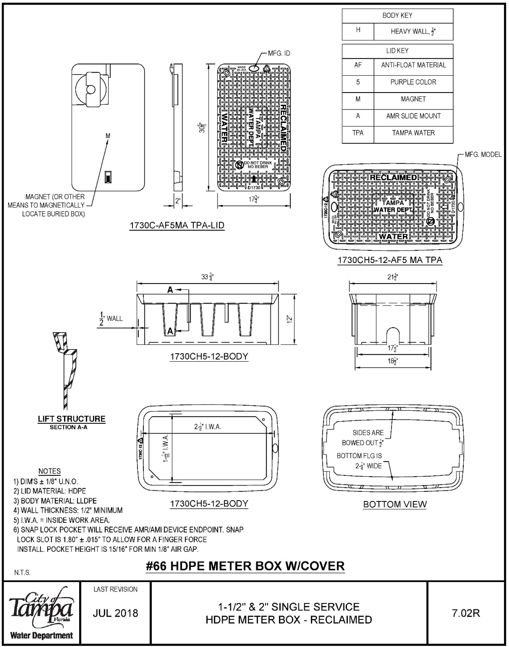
- MAGNET (OR OTHER MEANS TO MAGNETICALLY LOCATE BURIED BOX)
- LIFT STRUCTURE
- SECTION A-A
- NOTES
- 1) DIM'S ± 1/8" U.N.O.
- 2) LID MATERIAL HOPE 1730C-AF5MA TPA-LID 1730CH5-12-BODY 2I.W.A.
- 3) BODY MATERIAL: LLDPE 1730CH5-12-BODY
- 4) WALL THICKNESS: 1/2 MINIMUM
- 5) I.W.A. = INSIDE WORK AREA.
- 6) SNAP LOCK POCKET WILL RECEIVE AMR/AMI DEVICE ENDPOINT. SNAP LOCK SLOT IS 1.80" ± .015" TO ALLOW FOR A FINGER FORCE INSTALL. POCKET HEIGHT IS 15/16" FOR MIN 1/8" AIR GAP.
- BODY KEY H HEAVY WALL, ' LIDKEY AF ANTI-FLOAT MATERIAL PURPLE COLOR M MAGNET A AMR SLIDE MOUNT TPA TAMPA WATER 1730CH5-12-AF5 MA TPA 21-' IT L_ EE□ SIDES ARE BOWED OUT A' BOTTOM FLG IS 2. WIDE
- BOTTOM VIEW N.T.S. #66 HOPE METER BOX W/COVER
- Water Department LAST REVISION JUL 2018
- 1-1/2" & 2" SINGLE SERVICE HOPE METER BOX -RECLAIMED 7.02R
6.0 Version History
| Version # | Revision Date | Revision By | Reason |
|---|---|---|---|
| E_1.2_TWD Development Manual_20200512 | 5/12/20 | BDP | 1) Maximize ADA compliance 2) Maximize gender neutral verbiage 3) Update, consolidate or rescind the following documents:
|
- Memorandum dated 06/15/94 metering of duplexes
- E_5.1_TWD Water Pipe Network As-Built Requirements Manual dated 11/14/18
Upon E_1.2_TWD Development Manual_20200512 becoming effective these documents shall be rescinded and replaced by this E_1.2_TWD Development Manual_20200512.
7.0 RASCI Model STAKEHOLDERS
The TWD’s RASCI Model stakeholders for this controlled document are as follows:
- R (Responsible) – Chief Engineer
- A (Accountable/Approver) – Water Department Director
- S (Supportive) – Asset Management Engineers, Design Engineers, Development Services Engineers
- C (Consulted) – Distribution Division Operations Supervisor, Asset Management Engineers, Design Engineers, Development Services Engineers
- I (Informed) – Water Department staff, Development Services Center staff, local developer professional organizations and engineering firms